WIP
- Reader LEDs not installed
TODO
- Add results for reader LEDs
Proceed with Caution
Careful when making the harnesses for this part
You will need at least 24 AWG wire for most connections, specially for feeding +12V to the LEDs, and also keep the same gauge size for grounds. Wires that carry signals should be fine with smaller gauge.
In my case I did everything with 22 AWG just to be safe. In the list below you can find already built harnesses for the needed connectors, although some may differ from what I used.
Bill Of Materials
If any link stops working, just try to searching for the piece in specific for the time being, you’ll probably find it.
DC OUT (for feeding the LEDs):
- VLP-04V
- Connector and terminals: https://es.aliexpress.com/item/1005009428438124.html
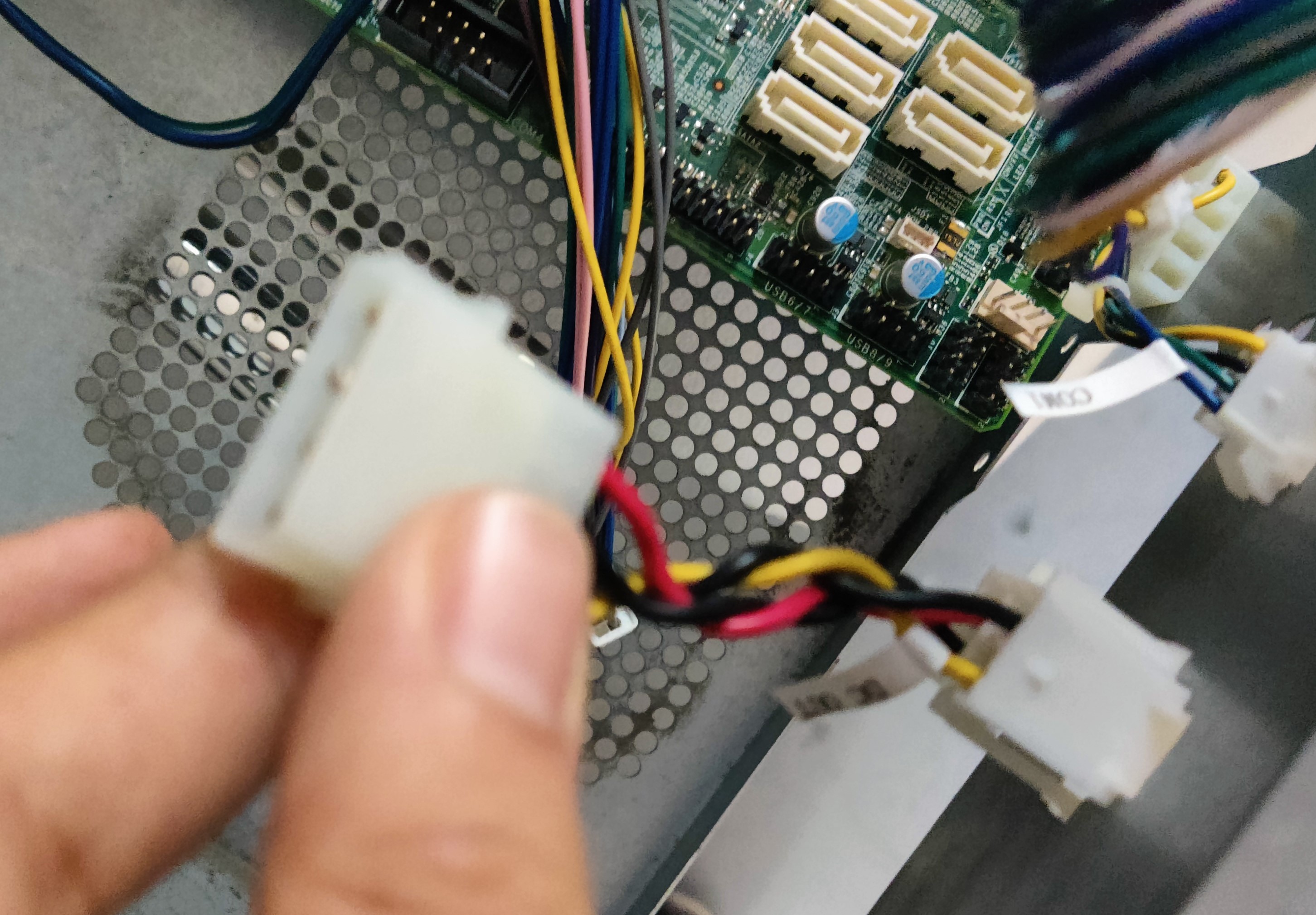
- Alternatively, draw 12V directly from PSU by plugging some molex
- https://es.aliexpress.com/item/1005006026259742.html
CN10 (reader and woofer LEDs):
- XADRP-18V → XADR-12V
- XADRP-18V:
- 22 AWG Harness: https://es.aliexpress.com/item/1005009404019959.html
- Connector only: https://es.aliexpress.com/item/1005007898440466.html
- Terminals (SXA-001T-P0.6): https://es.aliexpress.com/item/1005004425152785.html
- XADR-12V:
- Connector: https://es.aliexpress.com/item/1005008366405192.html
- Terminals (SXAM-001T-P0.6): https://es.aliexpress.com/item/1005008545737745.html
CN19 (woofer blue light, turntable LEDs and turntable sensor):
- PHDR-20VS:
- 22 AWG harness: https://es.aliexpress.com/item/1005008082796097.html
- 24 AWG harness: https://es.aliexpress.com/item/1005009363053705.html
- Connector: https://es.aliexpress.com/item/1005008735680501.html
- Terminals (SPHD-001T-P0.5): https://es.aliexpress.com/item/1005003975795283.html
- Socket (plug doesn’t exist) - B20B-PHDSS:
- https://es.aliexpress.com/item/1005008318489480.html
- 26 AWG harness to PHDR-20VS (2x10P): https://es.aliexpress.com/item/1005005572943124.html
IC/W LED connector:
- XADR-12V → XADRP-12V
- XADRP-12V:
- 22 AWG Harness: https://es.aliexpress.com/item/1005009492628988.html
- Connector: https://es.aliexpress.com/item/1005008376807266.html
- Terminals (SXA-001T-P0.6): https://es.aliexpress.com/item/1005004425152785.html
- Woofer connector:
- XMP-05V → XMR-05V
- XMR-05V:
- Connector (terminals included): https://es.aliexpress.com/item/1005009346695309.html
- Terminals (SXM-001T-P0.6): https://es.aliexpress.com/item/1005008545862370.html
- XMP-05V:
- Connector: https://es.aliexpress.com/item/1005005678537487.html
- Terminals (SXA-001T-P0.6): https://es.aliexpress.com/item/1005004425152785.html
- Reader connector: PHR-5
- Directly into RGB light, lights are independent from reader signal
LED PCB connector:
- PHR-5
- 22 AWG Harness: https://es.aliexpress.com/item/1005009702800874.html
- Description says it’s 22 AWG, however the product itself was 24 AWG
- Connector and terminals: https://es.aliexpress.com/item/1005007441813591.html
- At least one for each pair of LEDs, since they are connected in series:
- 2 LED PCB per turntable + 1 cable for incoming data = 2 cables per TT
- 2 LED PCB per woofer + 1 cable for incoming data = 2 cables per woofer
- 1 LED PCB per reader = 1 cable per reader
- Total = 10 cables
RGB strip for missing lights:
This section contains all related documentation, notes and results related the process of setting up existing LED lights in a Tricoro cabinet to behave like the lights of a LM cabinet, while making use of the BIO2 dedicated connections that are already programmed for this purpose on LM cabinets.
DC OUT
According to the manual, all grounds are merged to the PSU’s ground, therefore you can use the DC OUT connection which the cable itself is an extension of the PSU’s molex. Alternatively you may use a molex cable and splice 12V and GND from it.
RGB Lights wiring outline
Planning
- According to LM’s manual, both +12V and GND are taken from DC OUT (PCB’s PSU), meaning that all related grounds to RGB LEDs close the circuit in the same ground would need to be connected to the BIO2 and finally the PSU, since the BIO2 also feeds from the PSU. This would be:
- TT LED colors
- Woofer LED colors
- Reader LED colors
- All LEDs GND pins
- Reader LEDs current and ground however might need to be taken from COM1, at least for the ground since +12V comes directly from PSU, ground is taken from PCB’s serial

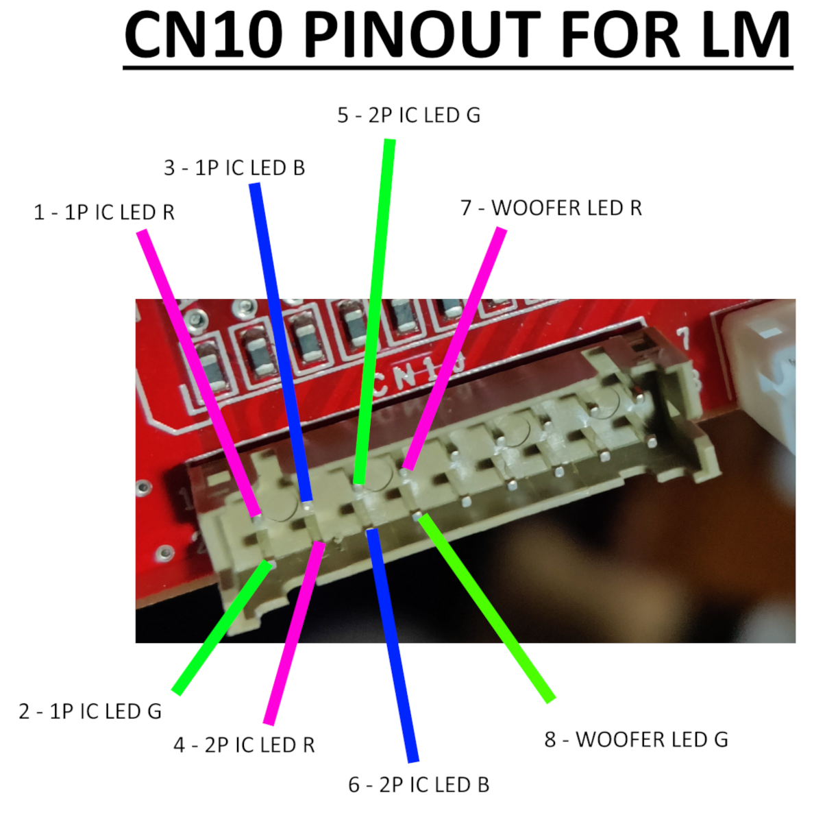
CN10
CN10 only carries color signal for both reader LEDs and red and green for woofers. Blue color for woofers is found at the first pin of CN19
Cable length should be atleast the following:
- Reader LEDs: ~80cm
- Woofer LEDs: ~180cm each, 200cm max.
- LED bridge cable length: 15cm
Following the main outline the relay board is completely ignored and cables go directly to the LED boards.
CN19
CN19 will be essentially the same as the pinout for BI2A: TT sensor signal and ground are on the same pins, while the rest are used for TT LED color signal. The +5V at pin 18 are used for TT photosensors but they already get fed so no need to rewire.
BI2A pinout

BI2X pinout

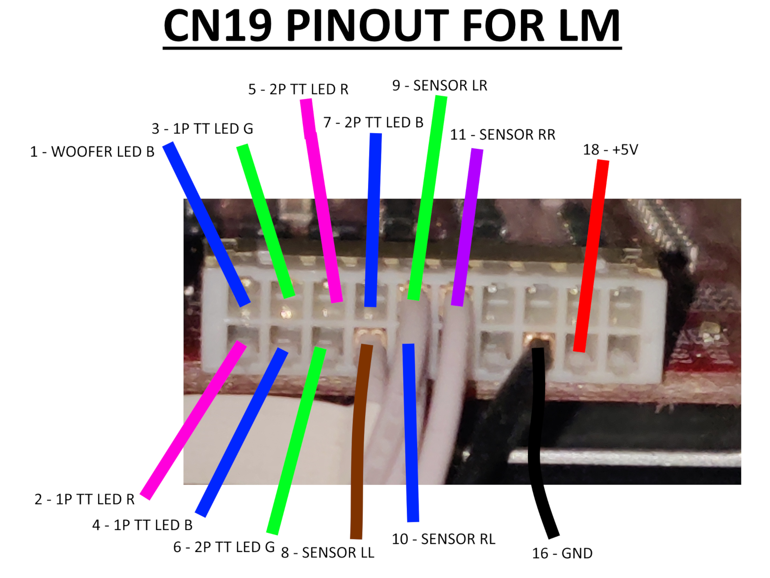
For TT sensor wires I soldered the necessary wires to a board socket connector, B20B-PHDSS, that pairs the PHDR-20VS, this choice is due to no plug connector existing so I had to approach it differently, but it works™ nonetheless.
Woofer LED B wire (pin 1) goes to IC/W LED cable, which bundles color signal wires for woofers and reader LEDs.
Cable length should be atleast the following:
- Turntable LEDs: ~150cm
- LED bridge cable length: 15cm
Following the main outline the relay board is completely ignored and cables go directly to the LED boards.
Woofers
- Woofer RGB connector: XMP-05V → XMR-05V
- LED PCB connnector: PHR-5
- LED bridge cable length: 15cm
- Cable length: ~180cm each, 200cm max.
- From last-end connector to LED PCB

Check CN10 very carefully
Apparently the connector for CN10 on the outer side of a CCJ PCB is inverted compared to how it comes out from the CN10 on BIO2 and how it is shown in the diagram above. So when making the harness take in mind the position of the connector and pay attention to which pins do the wires go from the CN10 connector on the BIO2 to the connector outside the PCB.
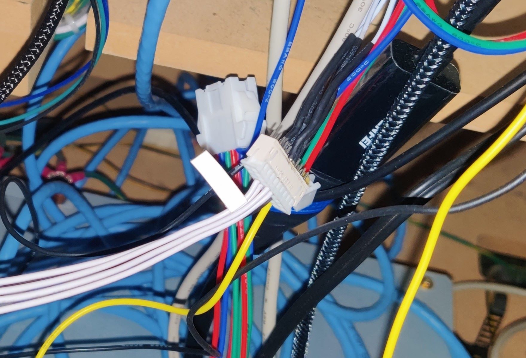
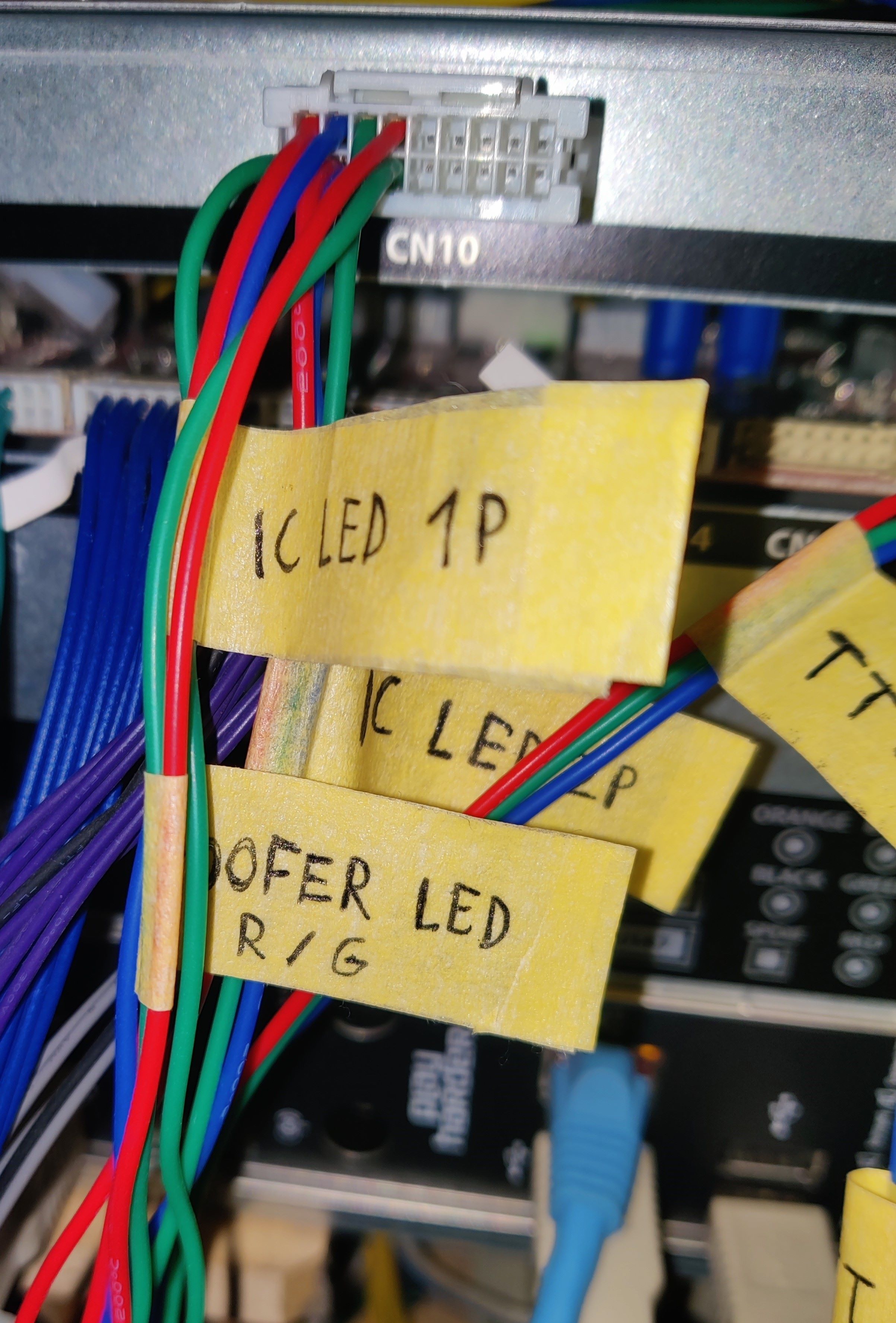
In my case after making the harness it ended up looking like this:
Instead of starting from pin 1 which would be the top left pin, in this case pin 1 is located at the bottom right.
All the wires from the CN10 and pin 1 from CN19 are grouped into the IC/W LED connector, which also carries 12V and GND for the woofers. For the readers, 12V and GND are taken from the COM1 connector instead, so in the end IC/W only feeds the woofer LEDs. (reference)
The remaining harnesses were built according to the diagram above. Do note that woofer color pins are spliced at some termination, resulting in two harnesses coming from one connector.
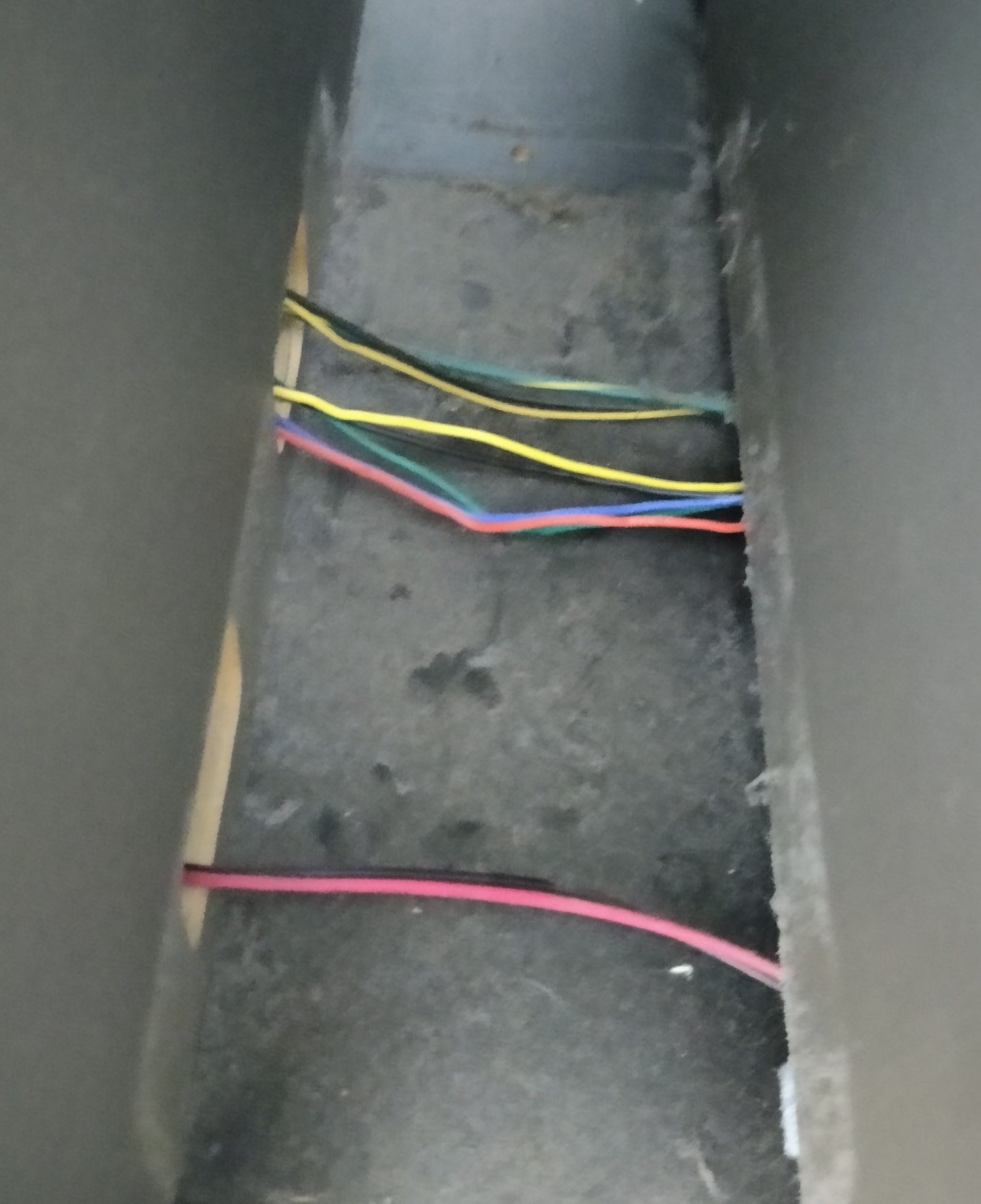
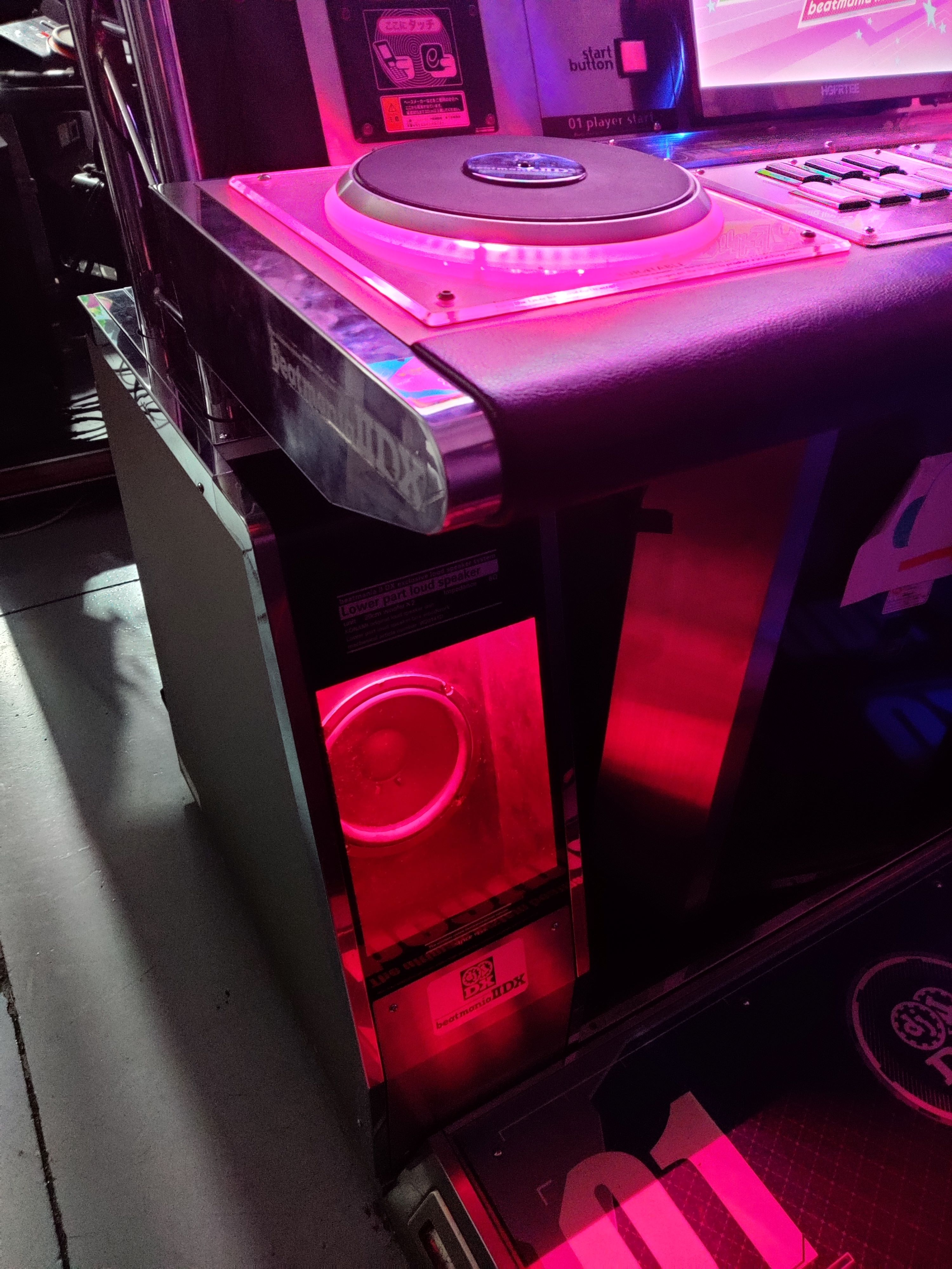
LED cables go through the woofer furniture from the inner side of the box (and covered with a small metal cover), which is separated from the outer side which is where the beams are secured.
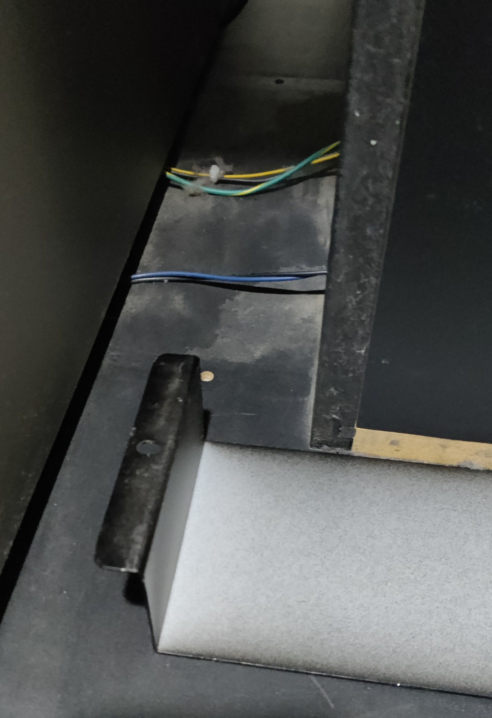 Section between the cab and the woofer where the wires for the speaker and LEDs are covered, with the metal sheet removed
You can access this side by taking off the speaker, which can be set very thight in place and you may need to apply some force with a tool like a flat screwdriver.
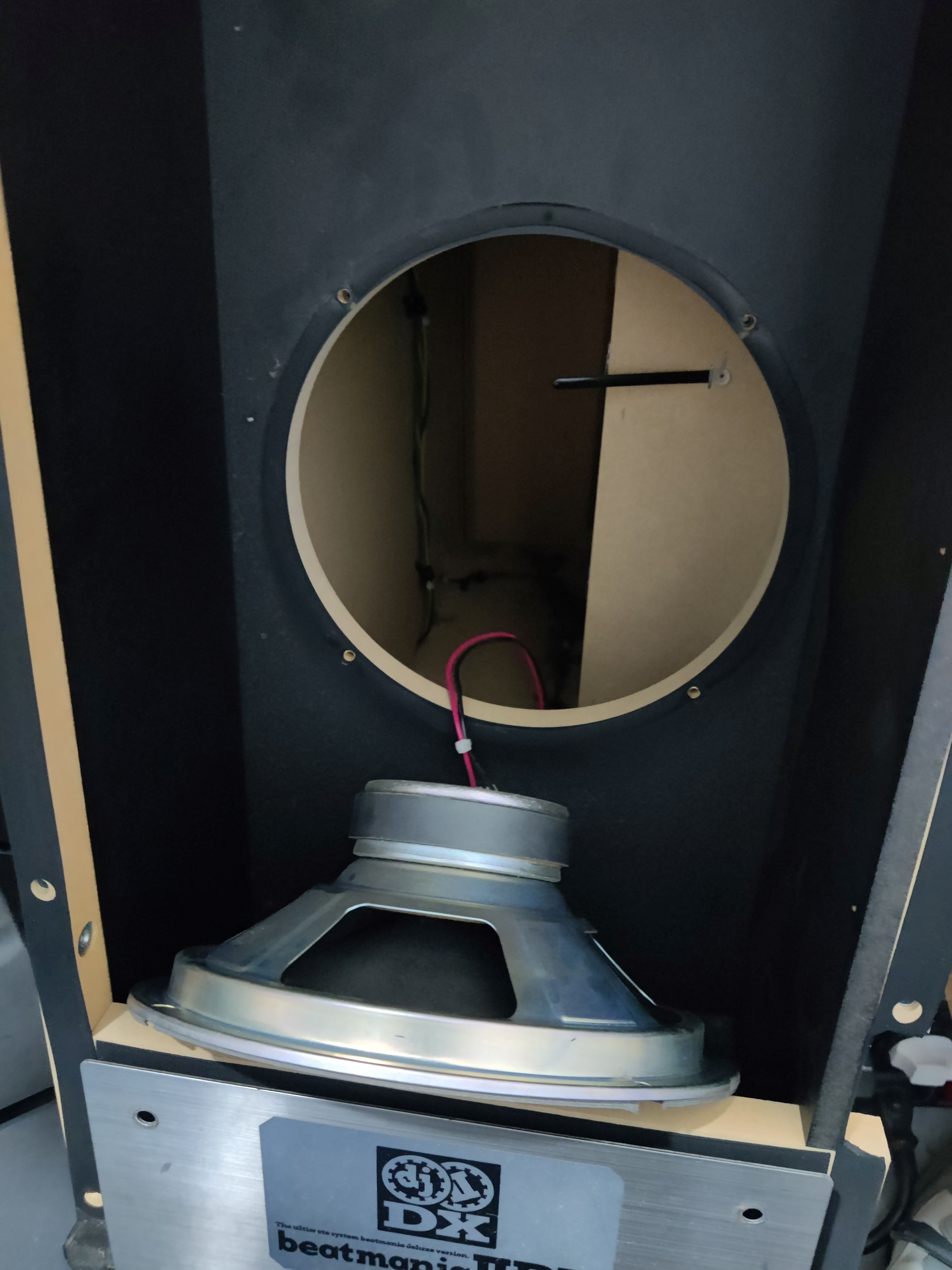 Woofer deattached off the box, showing the inside
Inside the woofer box you can see the holes that correspond to the ones in the pictures above, you will have to pass the harness through here in order to make it to the LED boards.
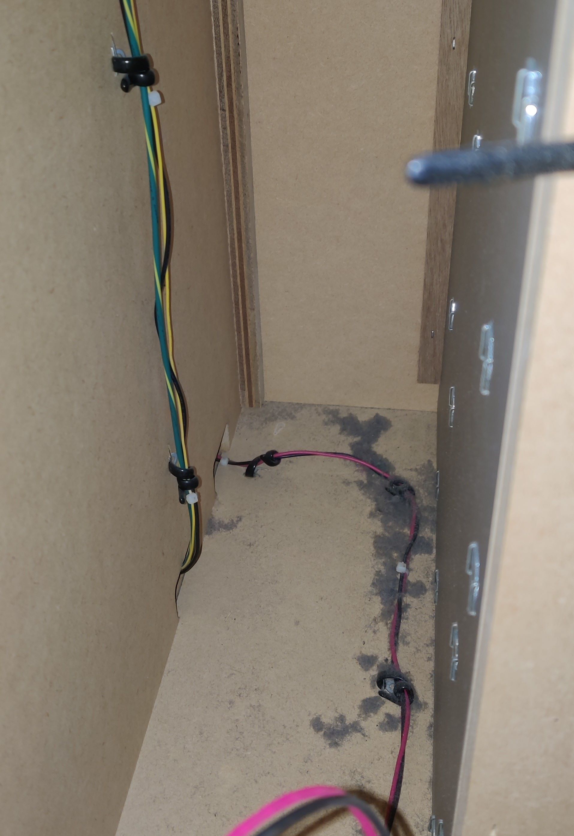
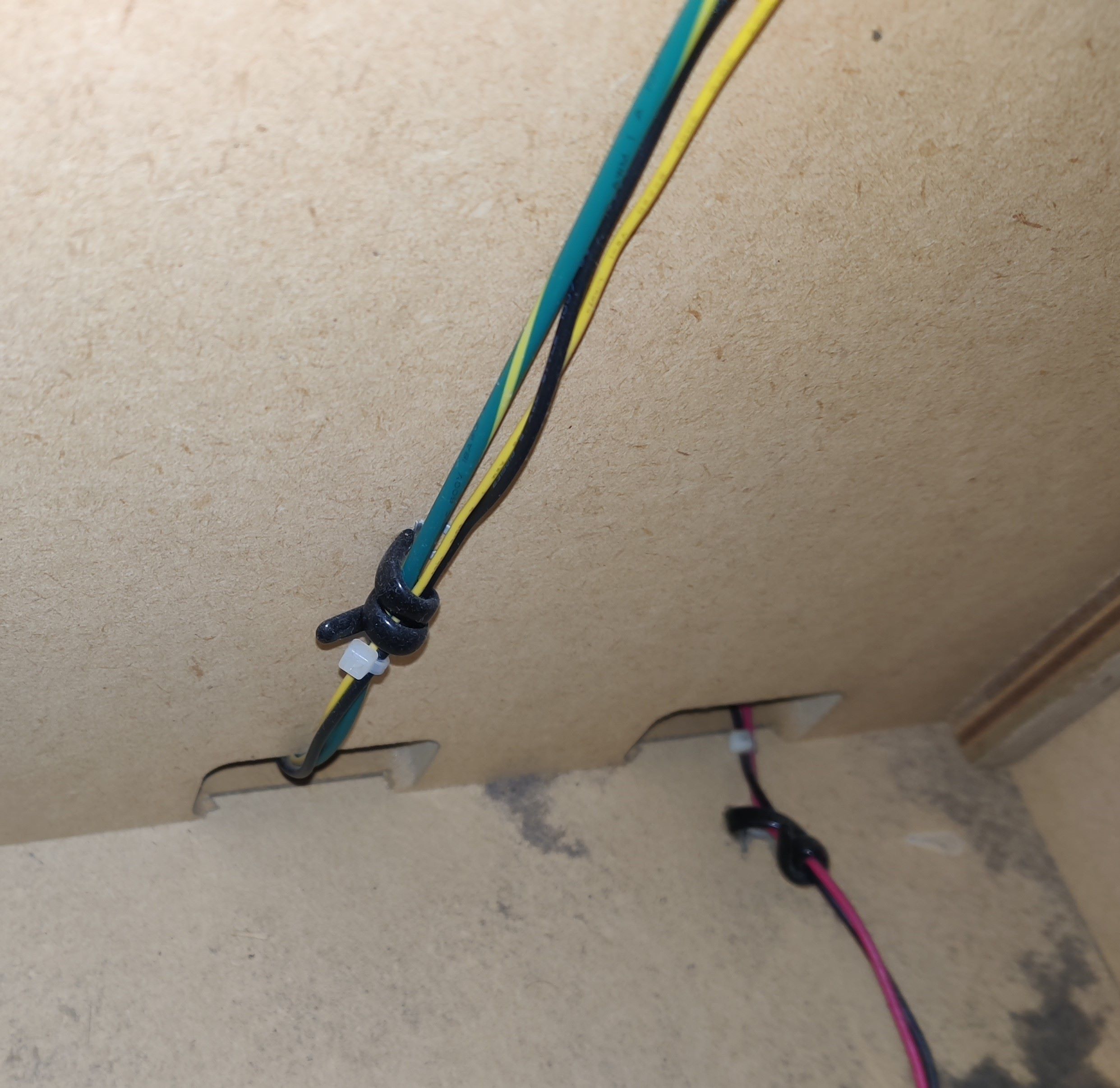
To pass the harnesses you may use one of the holes inside the cab that were shown in the Audio Jack section, in the same fashion as for the audio cables. The following pictures show through where I’ve been running the harness through up to the LEDs:
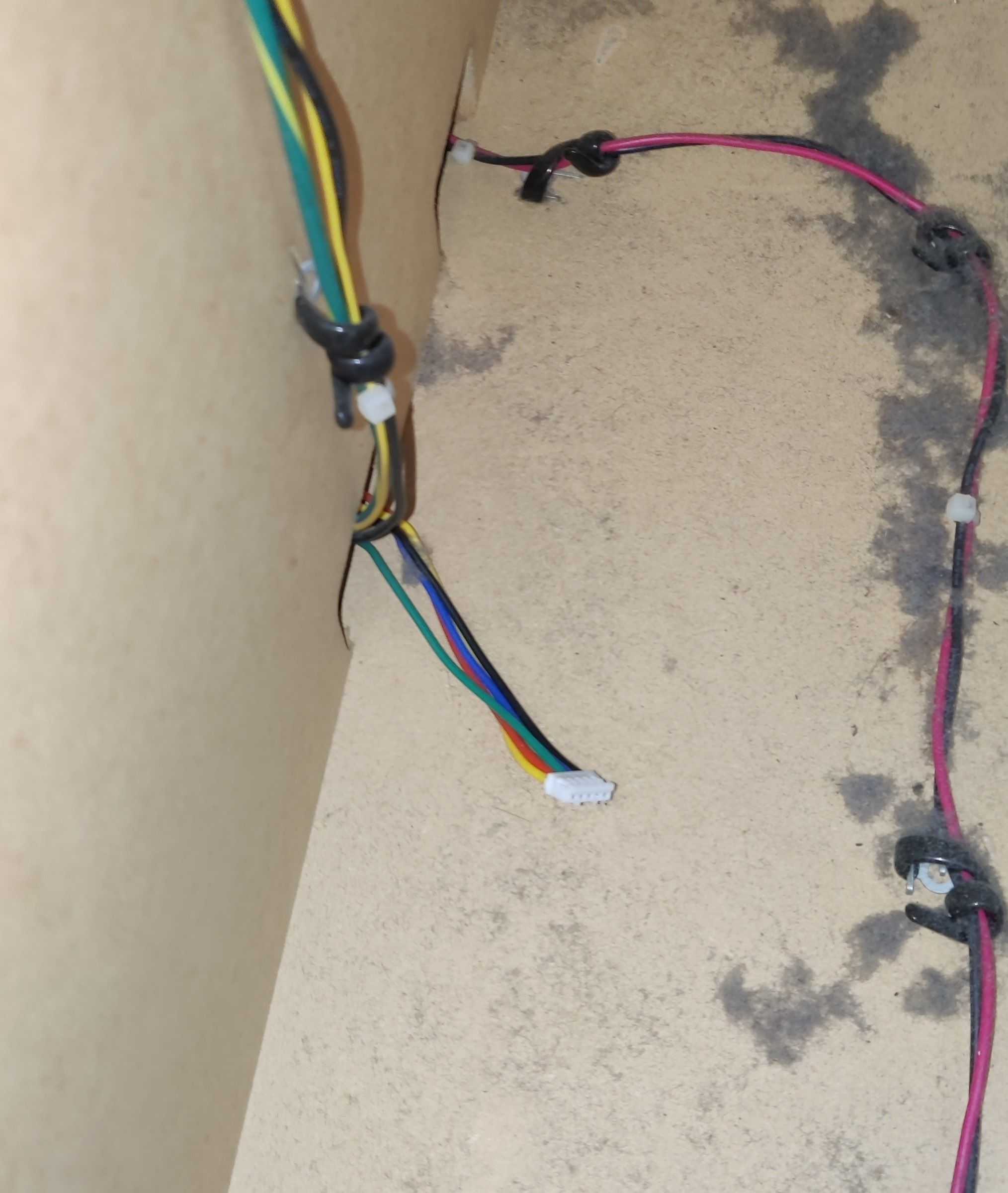
For this last section I’ve ran the harness through the same hole as the original harness, which is in the innermost corner (this is the P2 woofer, so it is located at the right).
In the way upwards you can find (or rather, touch) a knot where the original harness is held so it doesn’t fall through the hole, you may use it too for the new harness.
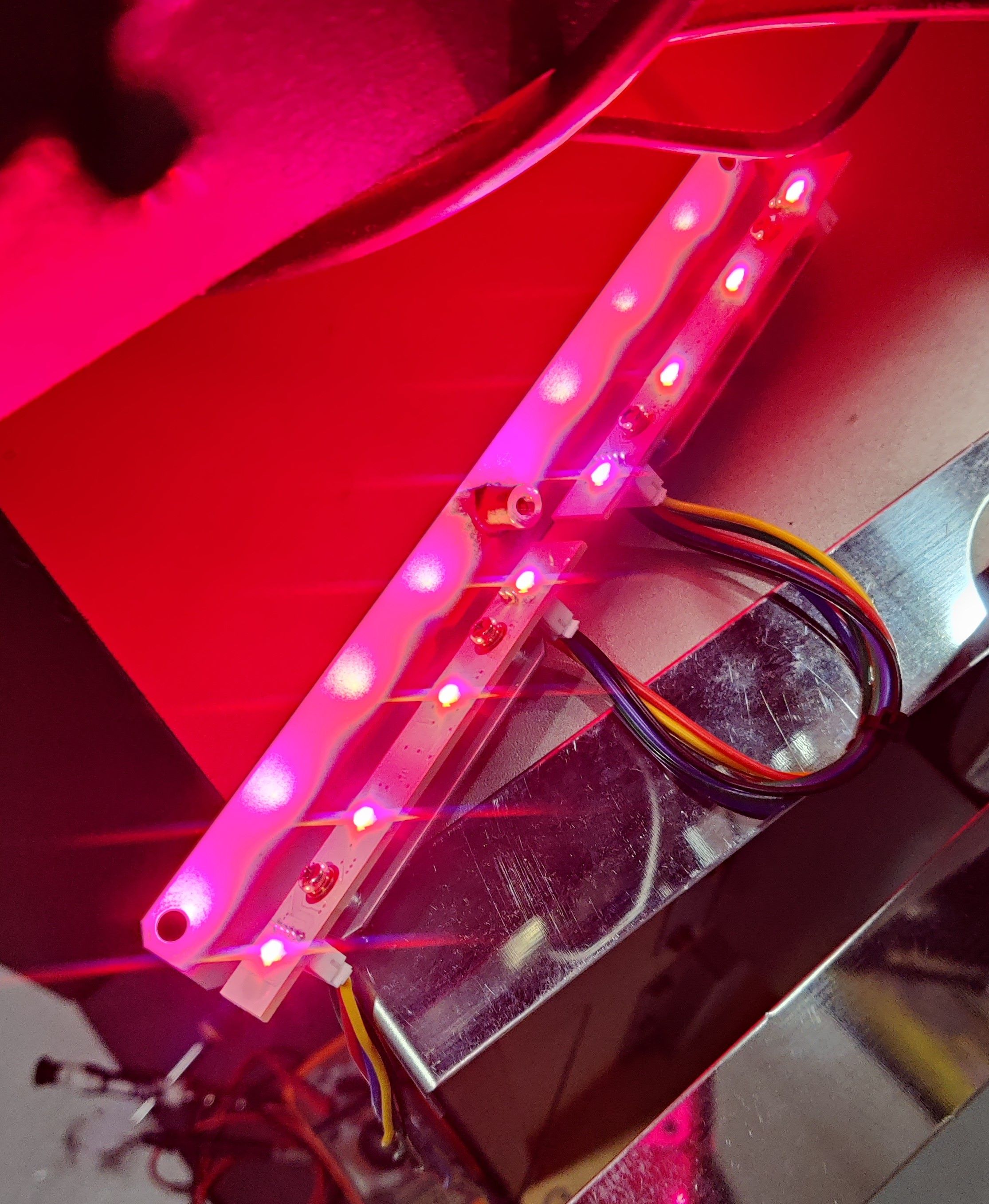
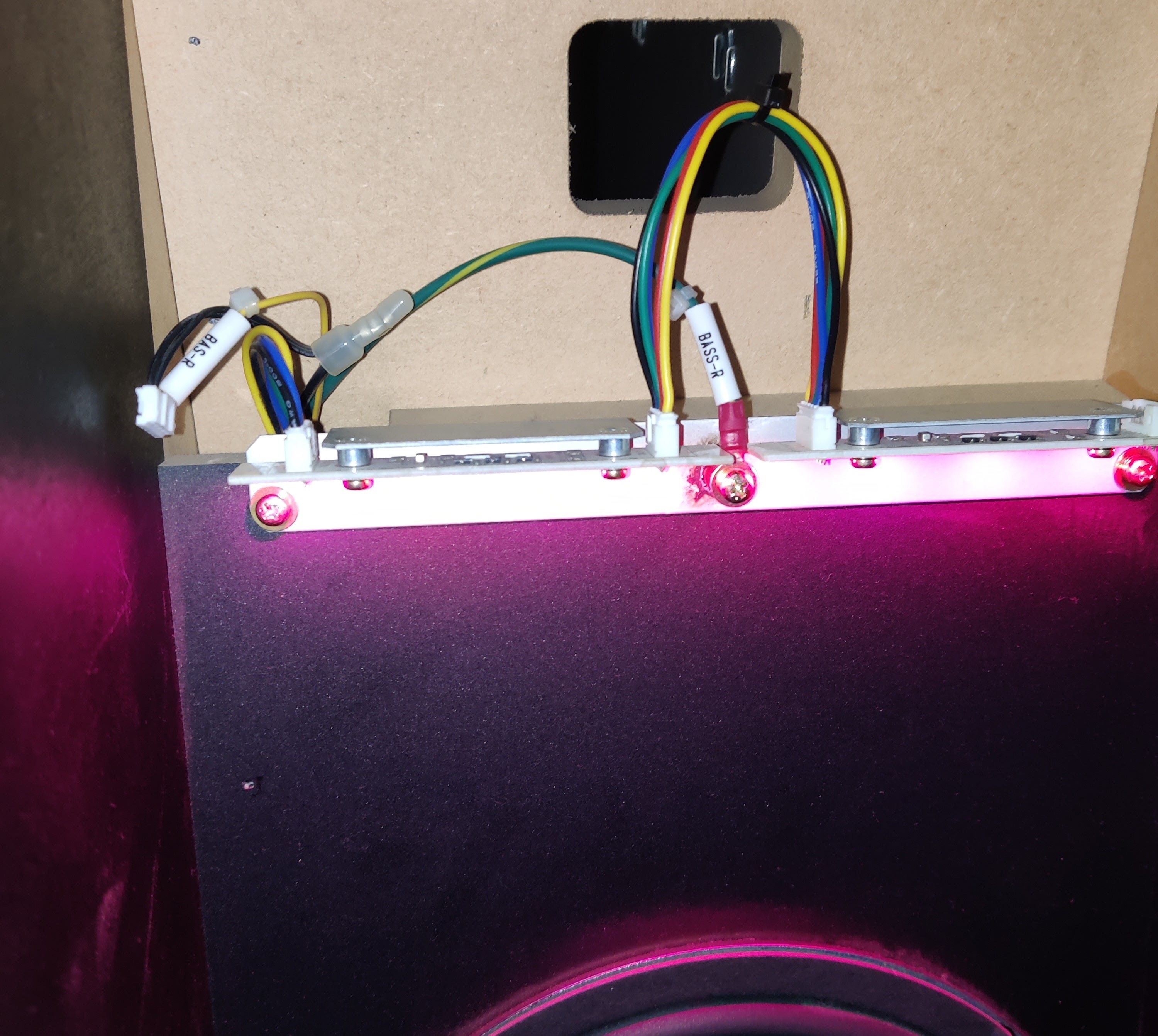 Woofer LED boards turned on and working with new harnesses
Readers
- LED PCB connector: PHR-5
- Lights are independent from reader signal
- Reader connector: XMR-05V → XMP-05V
- LED bridge cable length: 15cm
- Cable length: ~80cm each
- From last-end connector to LED PCB
WIP

Reader LEDs current and ground are being taken from COM1, +12V comes directly from PSU and ground is taken from PCB’s serial.
In this case I used pin 4 from COM1 to take current for the LEDs (benefiting from the workaround I did for the EPOLIS upgrade) and spliced the GND pin in order to merge both the ground for the serial and the lights. (reference)
The remaining harnesses were built according to the diagram above.
Turntables
- TT RGB connector: XMP-05V → XMR-05V
- LED PCB connnector: PHR-5
- LED bridge cable length: 15cm
- Cable length: ~150cm each
- From last-end connector to LED PCB

In order to be able to connect the TT sensor pins I used a B20B-PHDSS board socket to build an extension of the original CN19 harness (reference), I couldn’t find an actual plug connector for PHDR-20VS so I used this instead, which works anyway. If you don’t want to solder I linked a 26 AWG harness which has both connectors, but keep in mind that you would have to depin the terminals that correspond to the LED pins, at least for safety.
The remaining harnesses were built according to the diagram above.
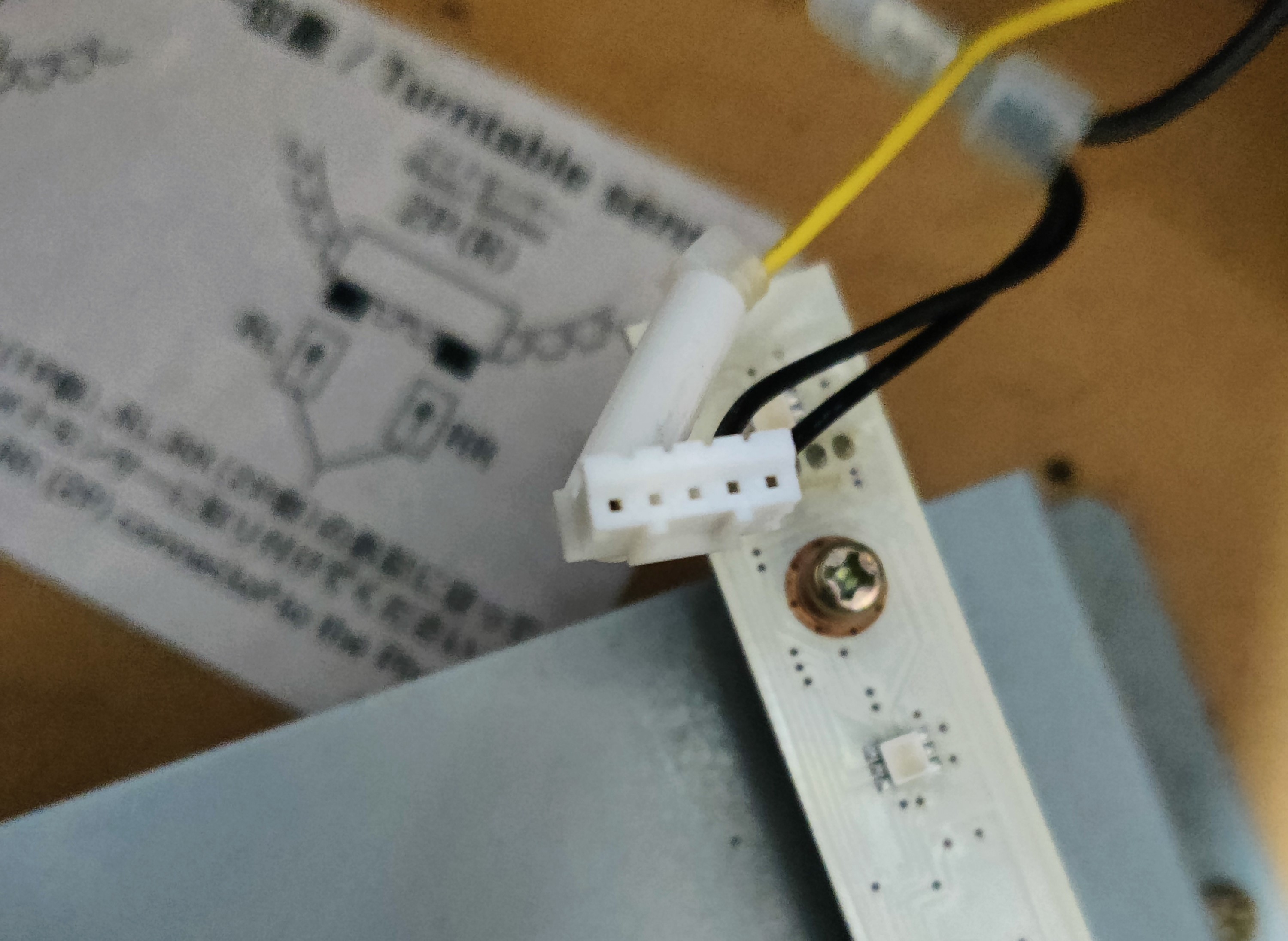
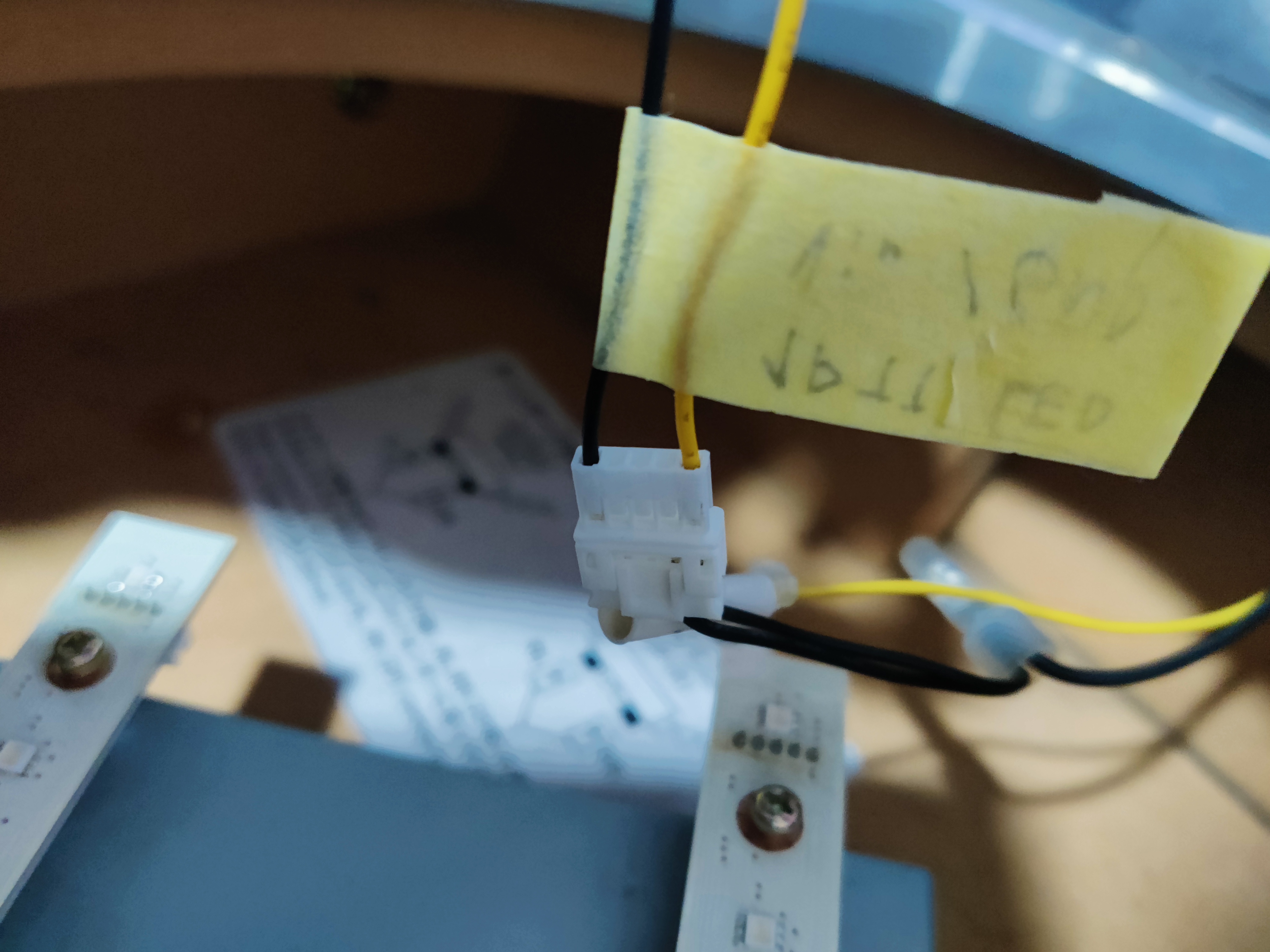
The following pictures show how the LED board connector looks when unplugged, I used this as reference when making the harnesses.
Results
CN19 (Turntables)
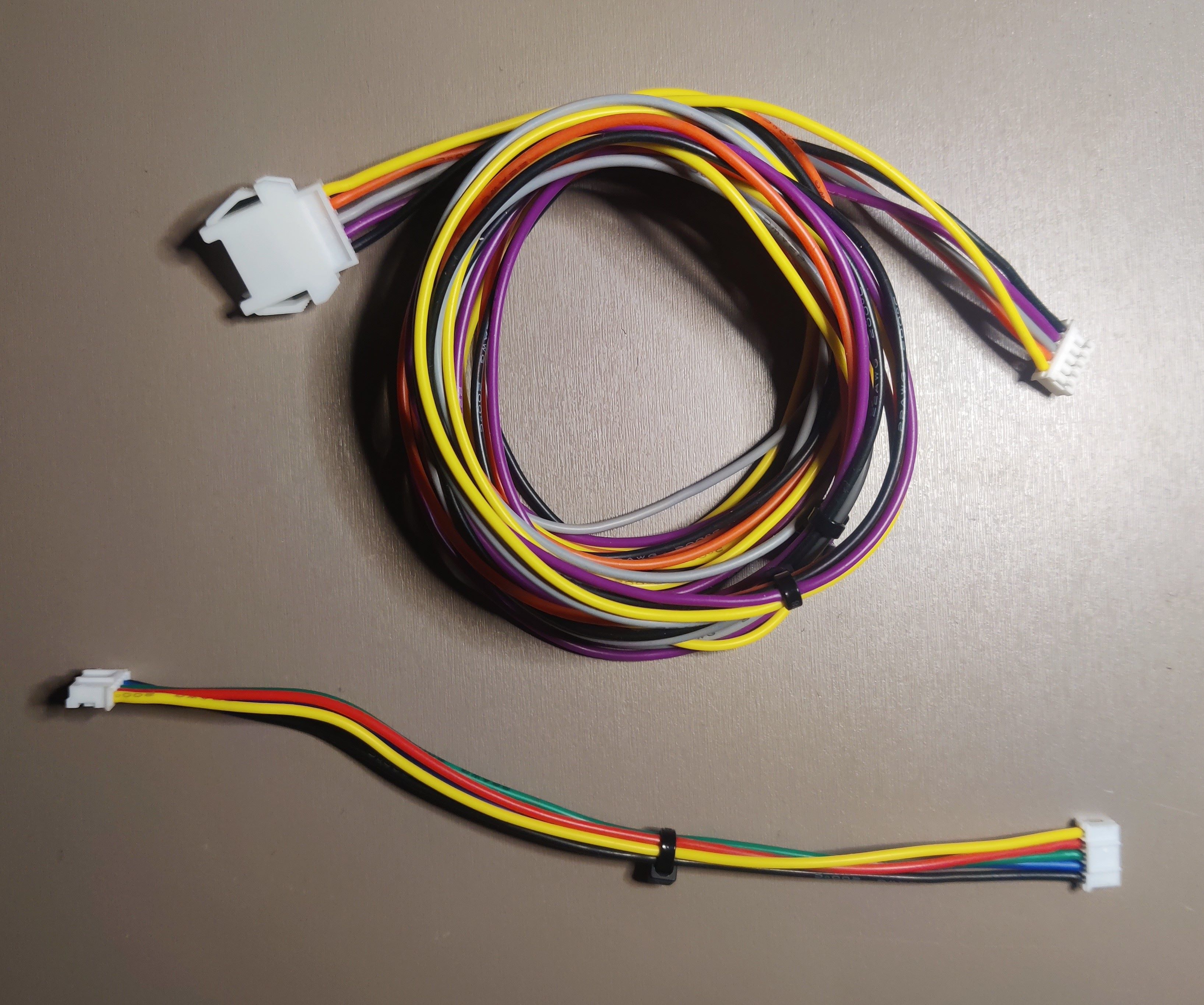 LED board harnesses, long one is the connection to the BIO2 source (plus voltage and ground), small one is the bridge between boards
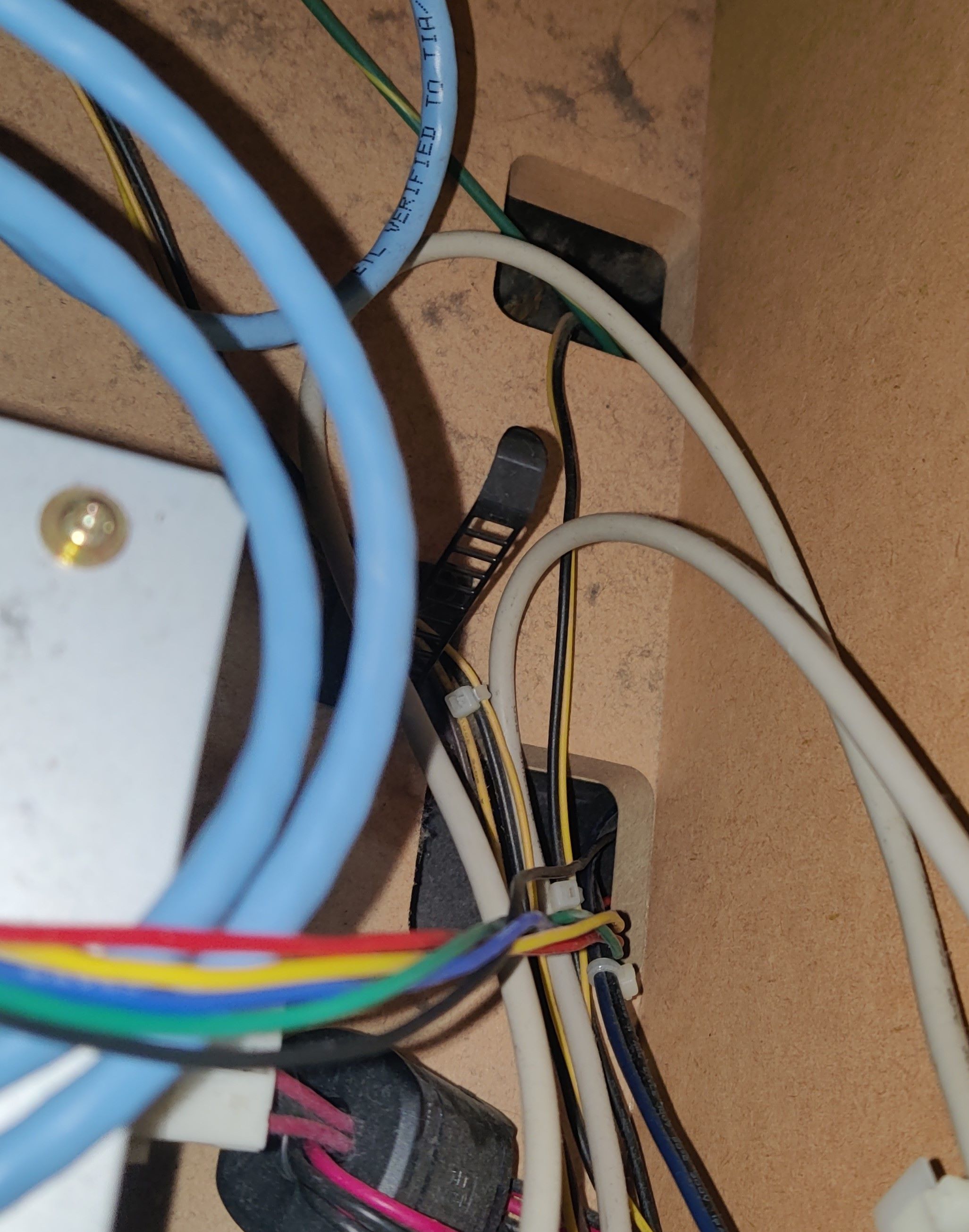
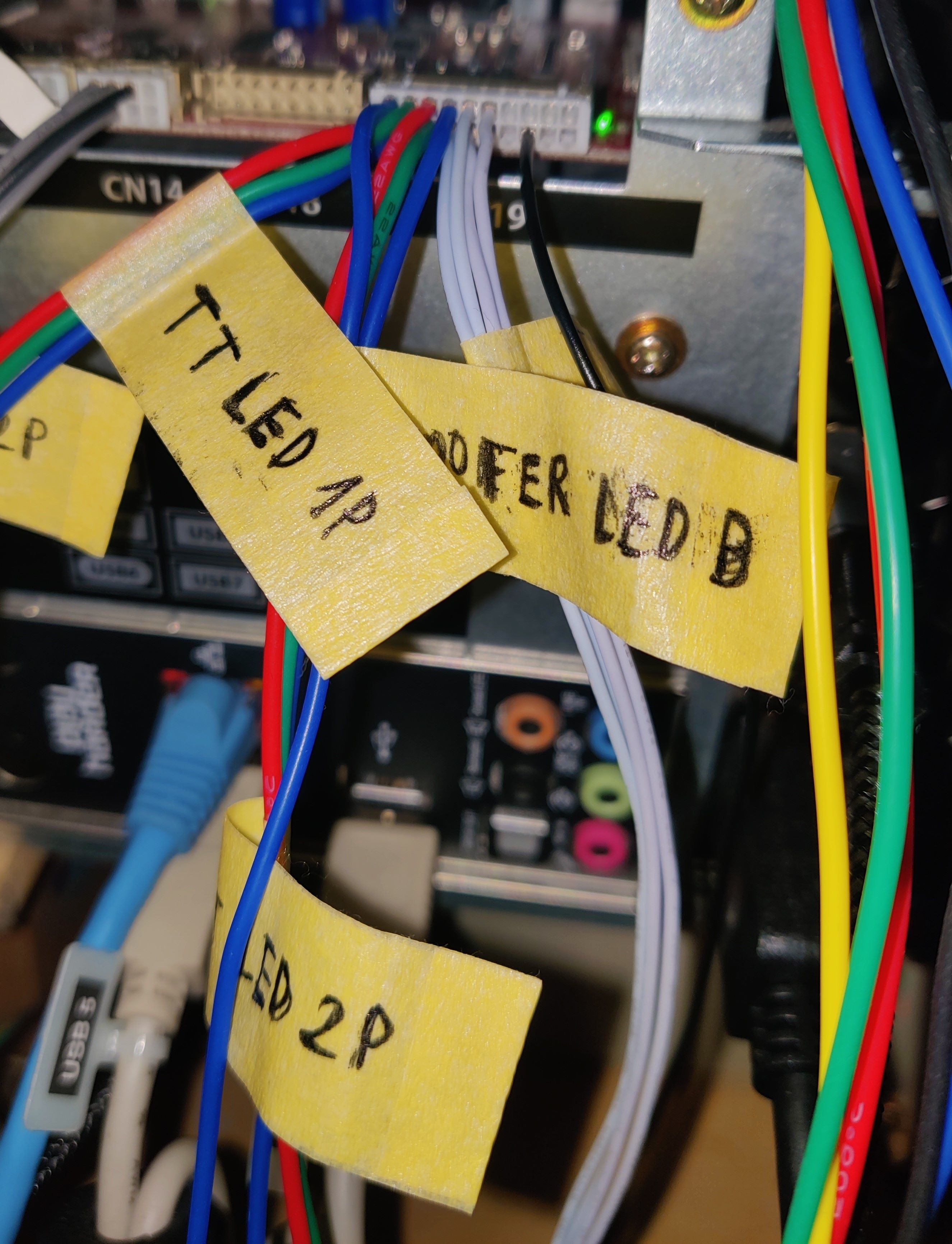
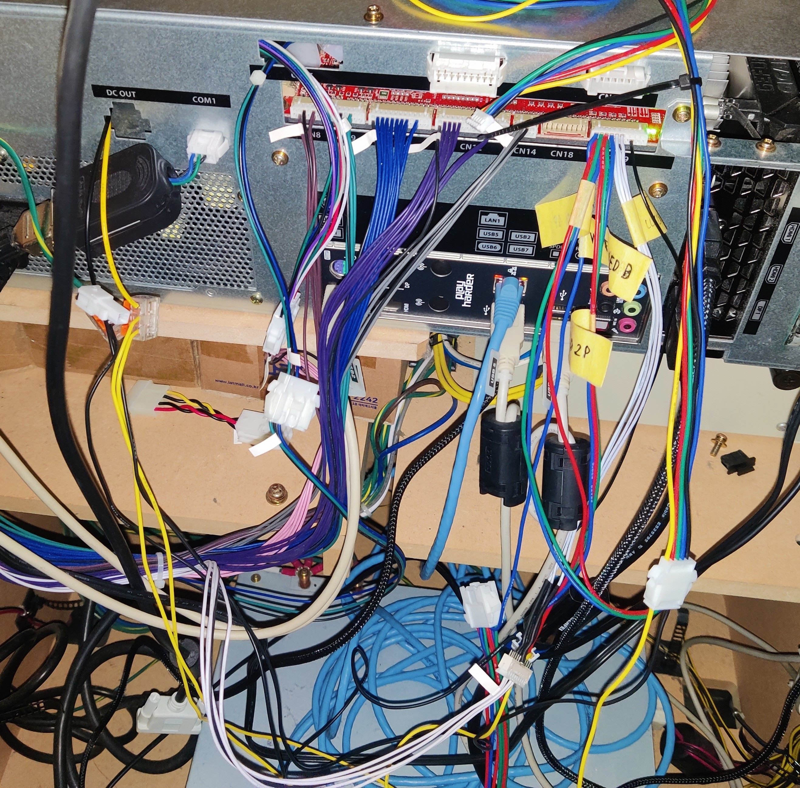 Messy cable distribution after adding the new harness for CN19, including the extension for the original CN19 harness and how current is taken from the PSU
 New CN19 harness
 Extension of original CN19 harness
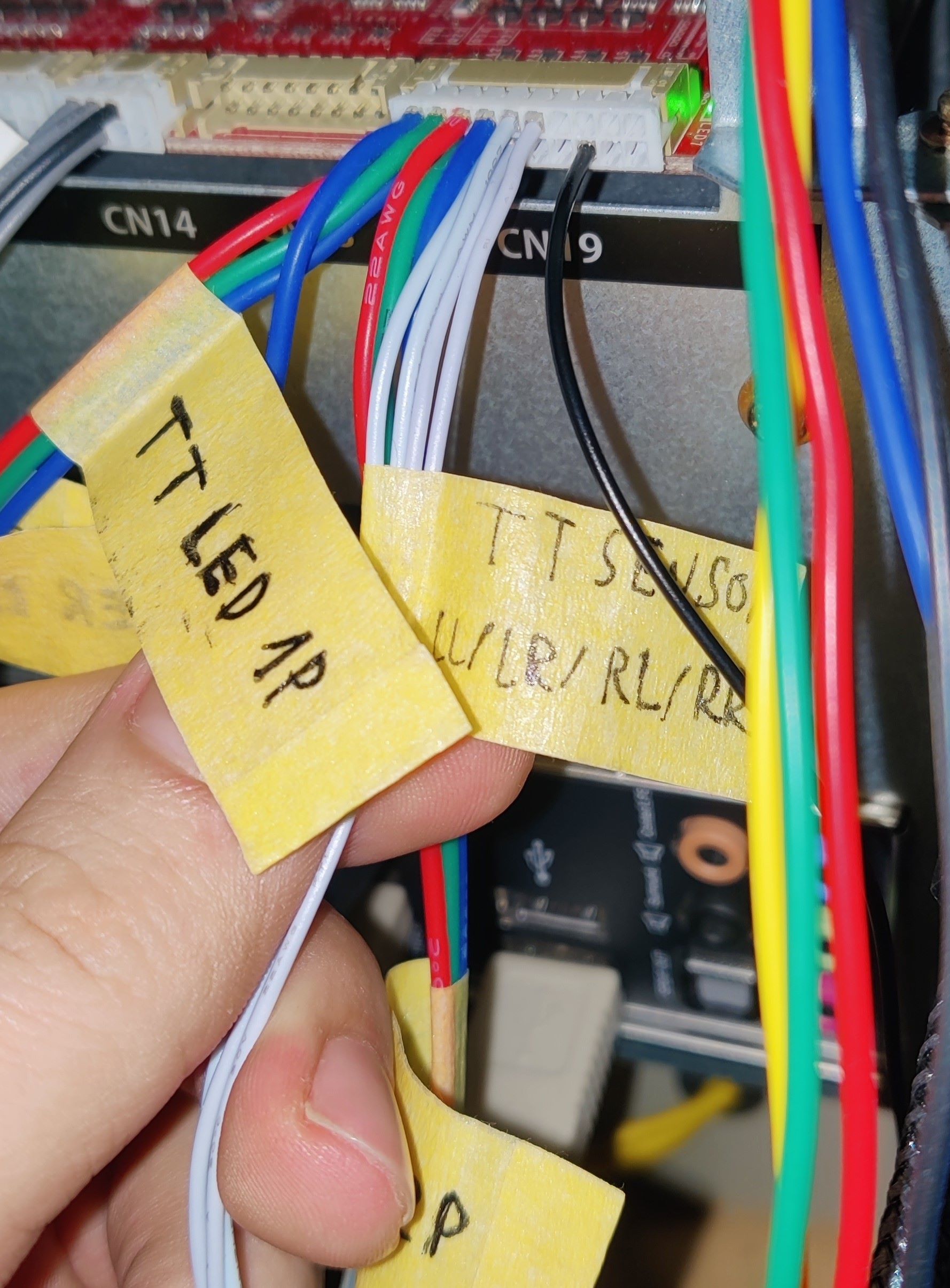 TT sensor wires from CN19 harness
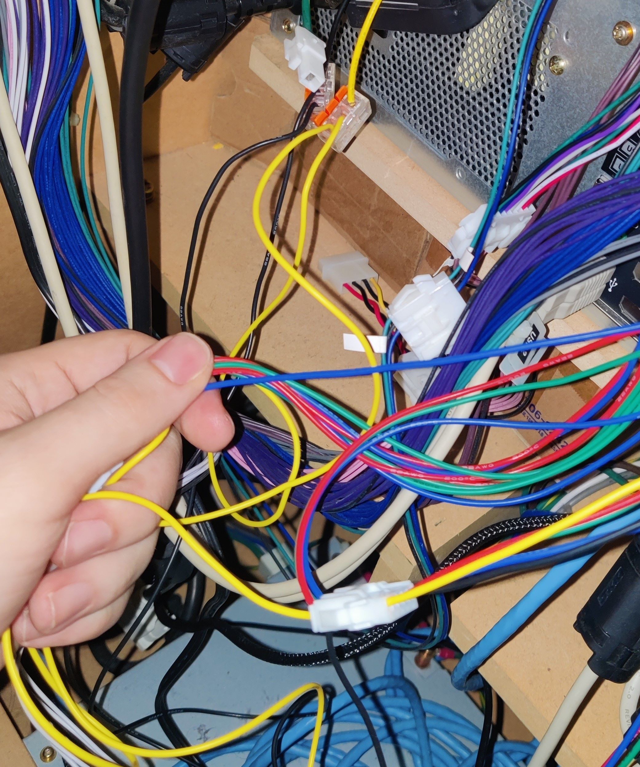 Harness and 12V and GND connections from the PSU
 Testing the new harness
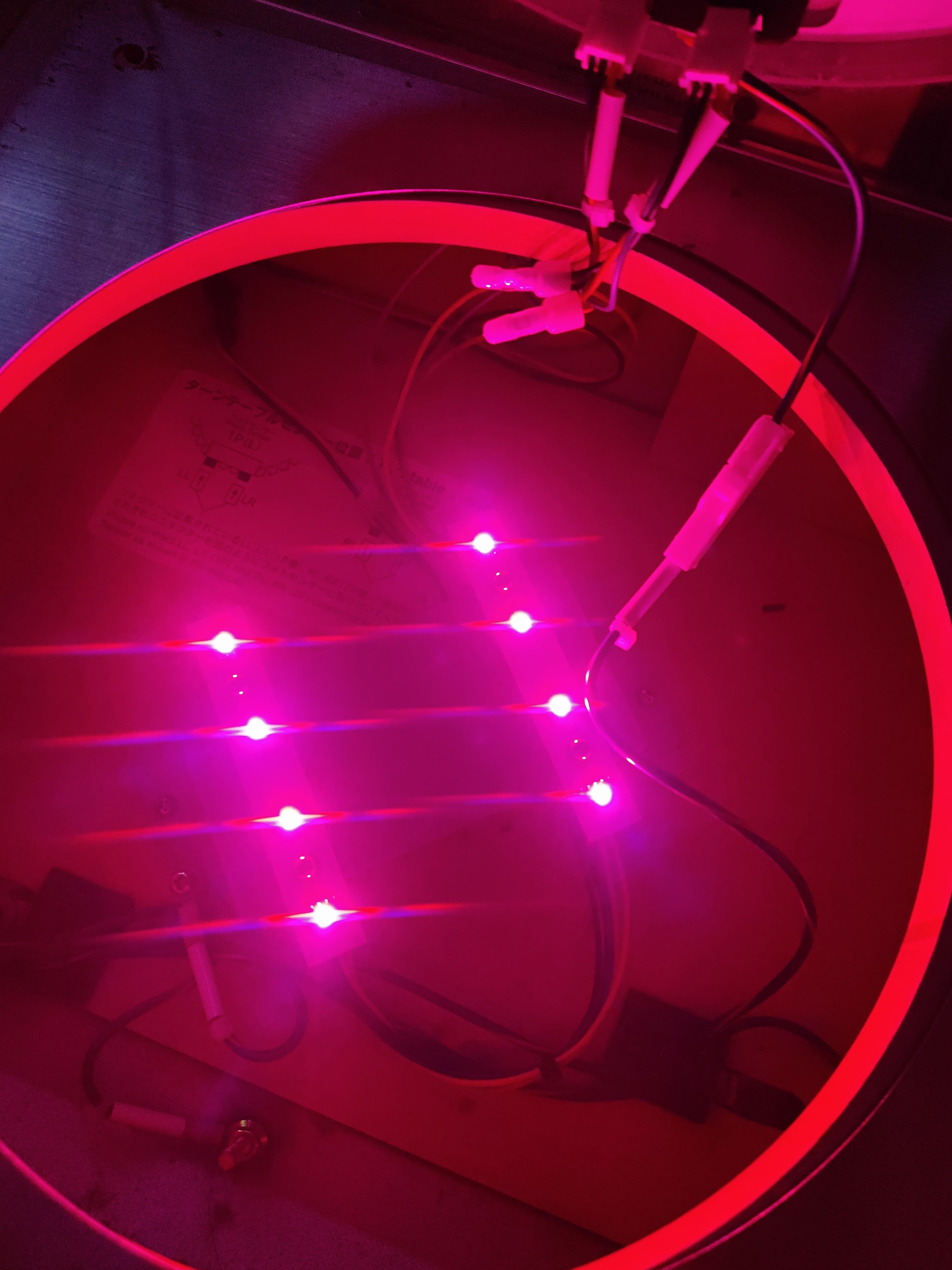
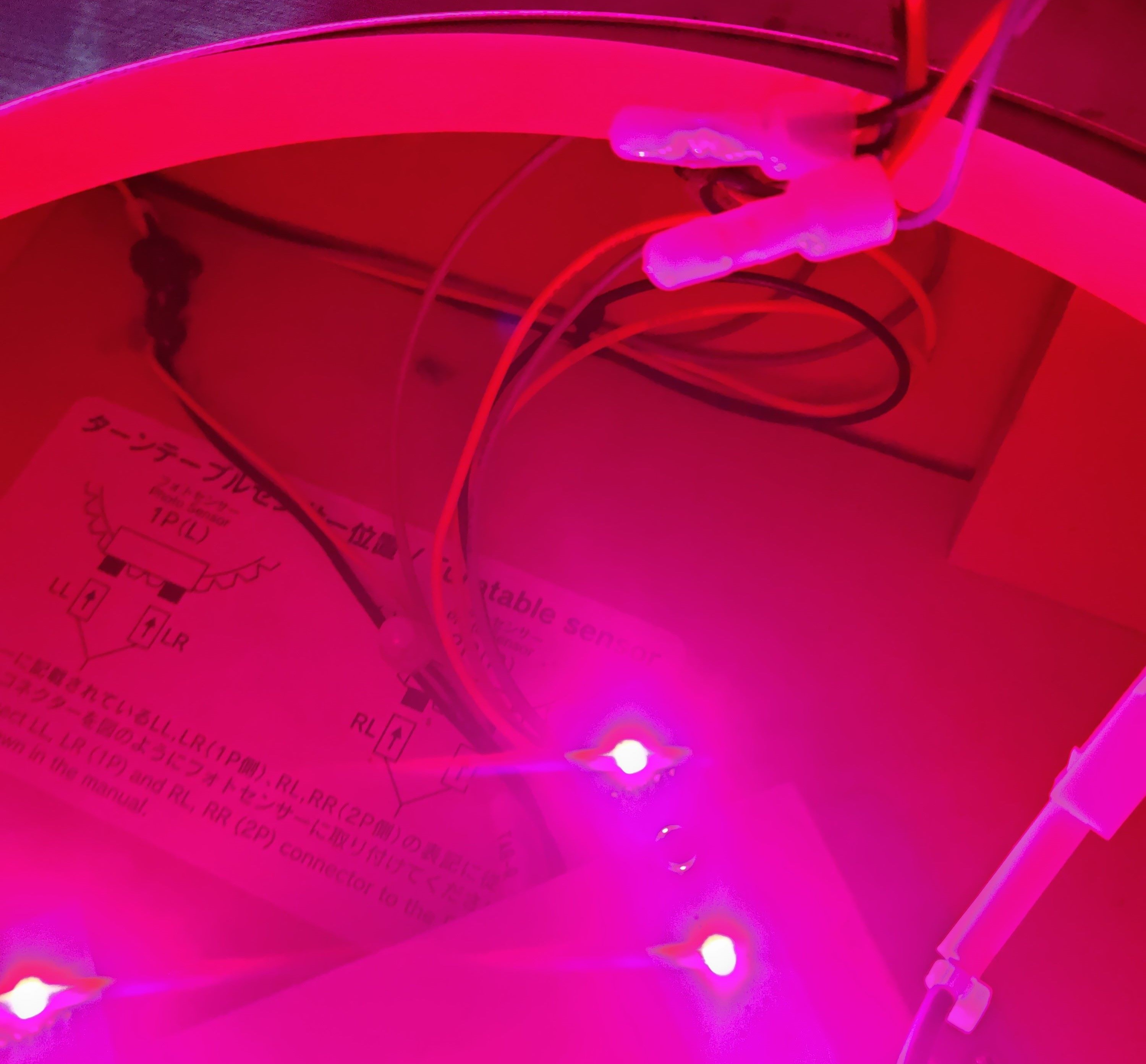
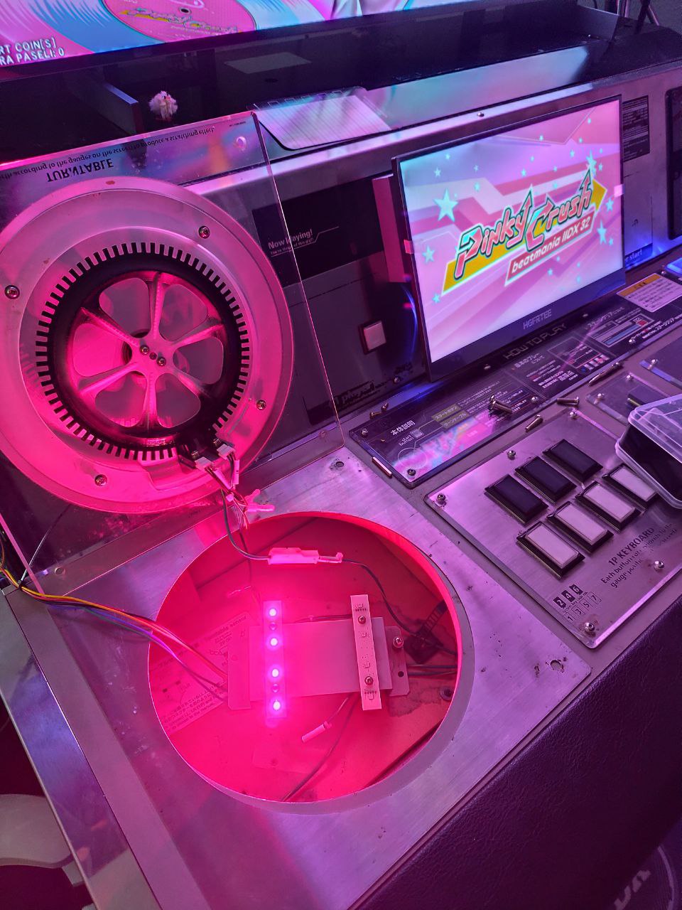
 Final look of the turtable LEDs
CN10 (Woofers and Readers)
Woofers results
 CN10 harness (wrong wiring, check Wooferssection)
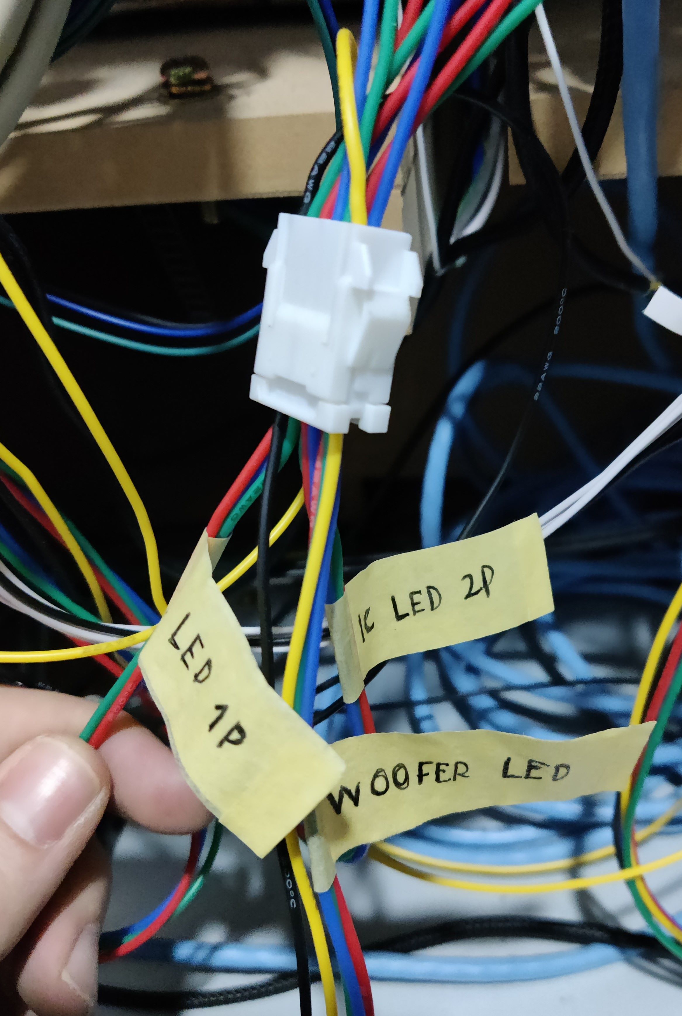 IC/W LED connector, grouping all conections for readers and woofers LEDs
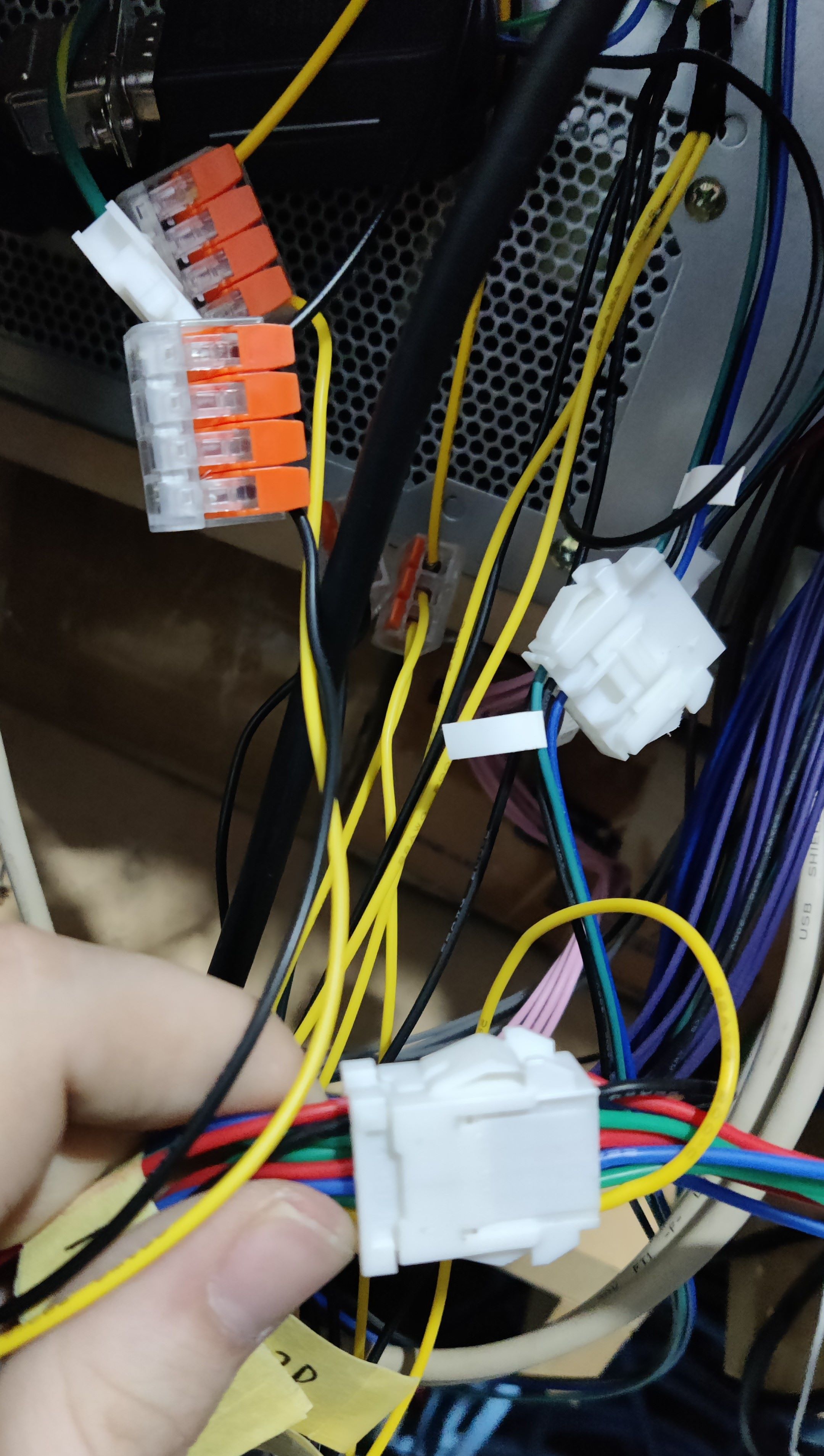 12V and GND taken from PSU into IC/W LED connector
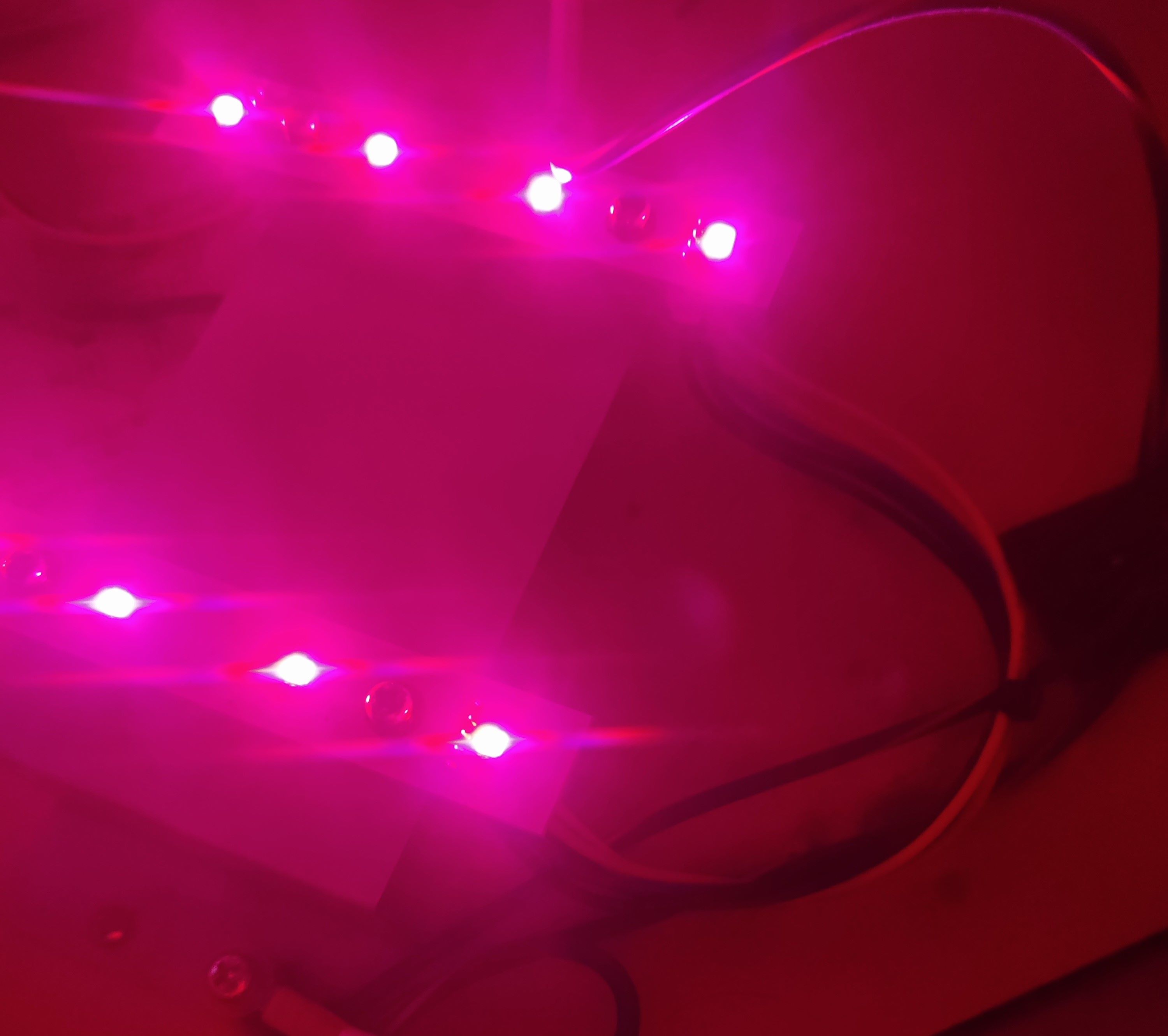
 Testing the new harness
 Final look on the woofer LEDs
Readers results
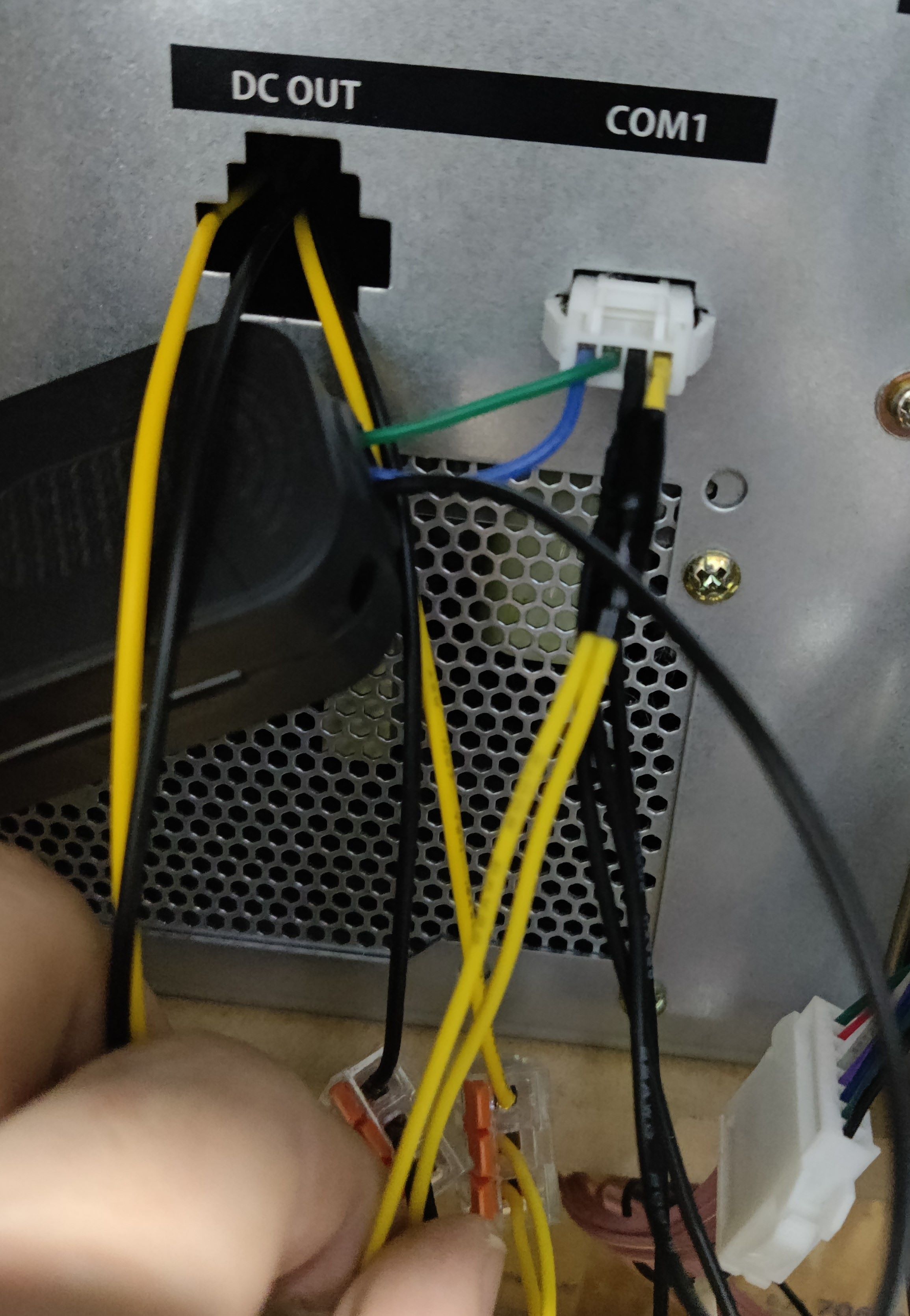 COM1 harness after adding wires for 12V and replacing the GND wire
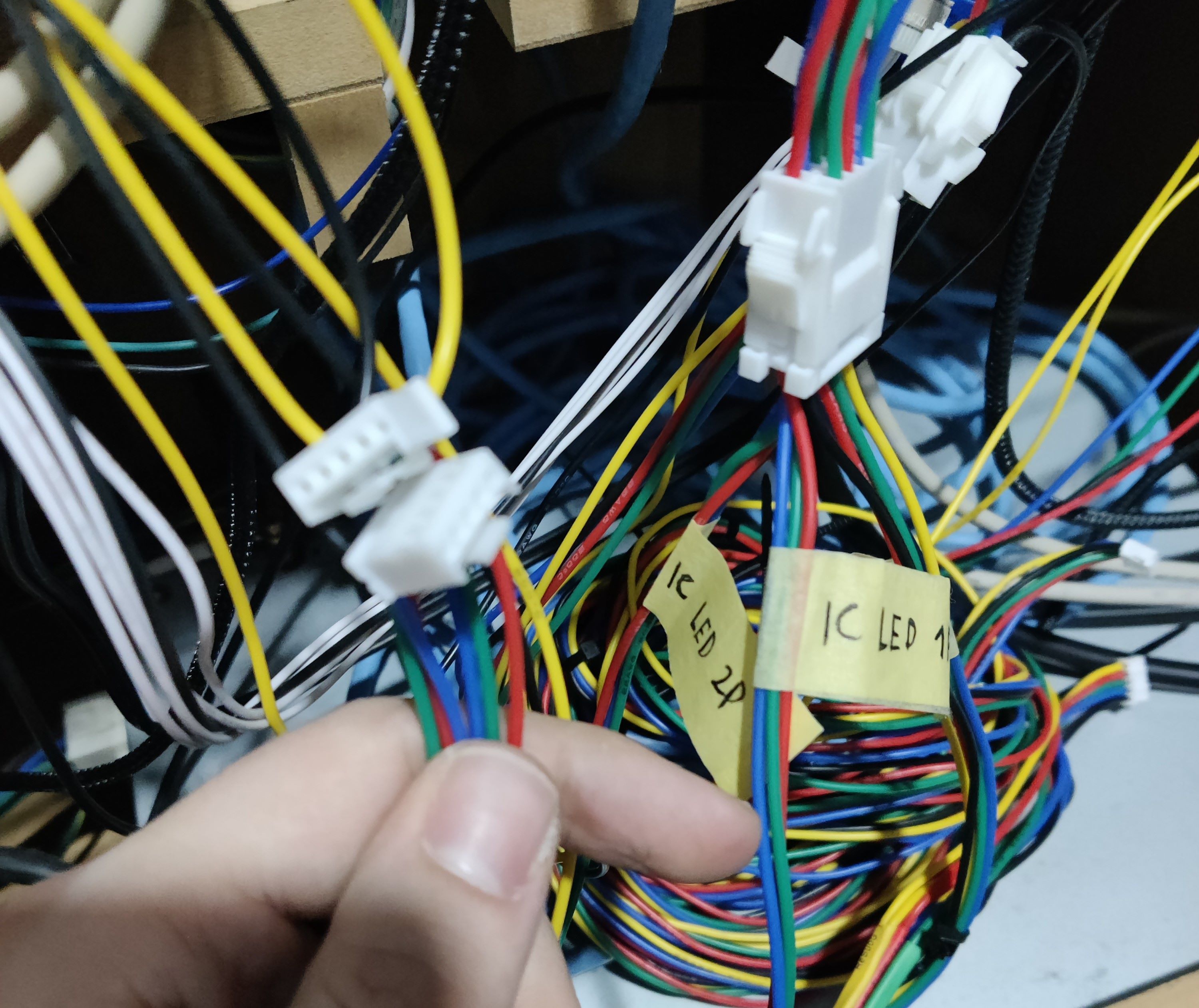 IC/W LED connector and IC LED connectors