Lightning Convert with Tricoro Cab
Further documentation
You might want check out @kokoseij’s guide for further documentation and details, especially for older IIDX cabinet versions:
Big shout out the Rhythm Game Cabs Discord server which is where I’ve gathered most of this info.
Regarding cabinet
This was done on a beatmania IIDX Tricoro cabinet.
This will be a continuation from a previous guide where I upgraded a IIDX Tricoro cabinet with a CCJ PCB in order to be able to play versions from RESIDENT and beyond. You may catch up with that guide first:
IIDX EPOLIS upgrade with CCJ PCB (Mirror)
Here I’ve tried to document and cover the upgrade of a IIDX Tricoro cabinet to a 120Hz/LM convert cabinet, with the addition of installing LED lights like in LM cabinets, as well as rewiring the existing leds for the turntables and woofers to light the same way as LM cabinets (RGB light depending on game) and also adding lights for IC readers. All done while keeping the cabinet’s furniture completely intact. I’ve also tried to merge in one place everything that I could investigate and read from different sources of information.
May anyone find this guide useful and serve as reference for anyone who wants to convert their cabinet or come up with differents solutions.
Feel free to DM me in Discord if you have questions: @elmiamiman
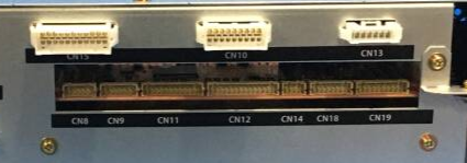
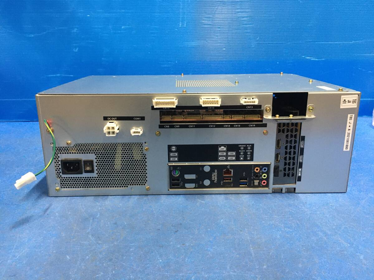
Relevant connectors:
- CN10: Woofer and Reader Lights
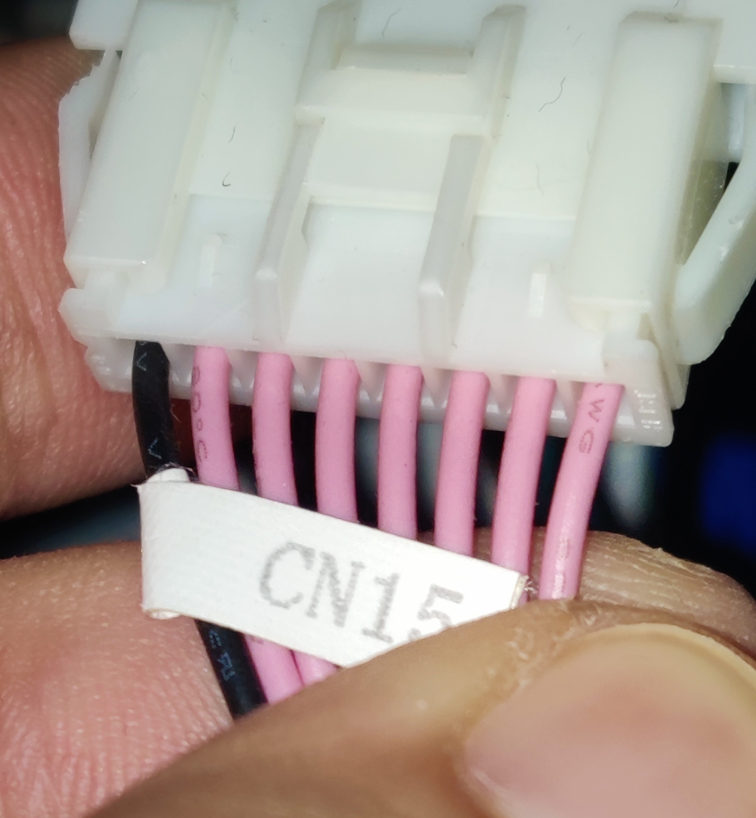
- CN15: 1P keys and Audio Jack
- CN18: WS2818b lights
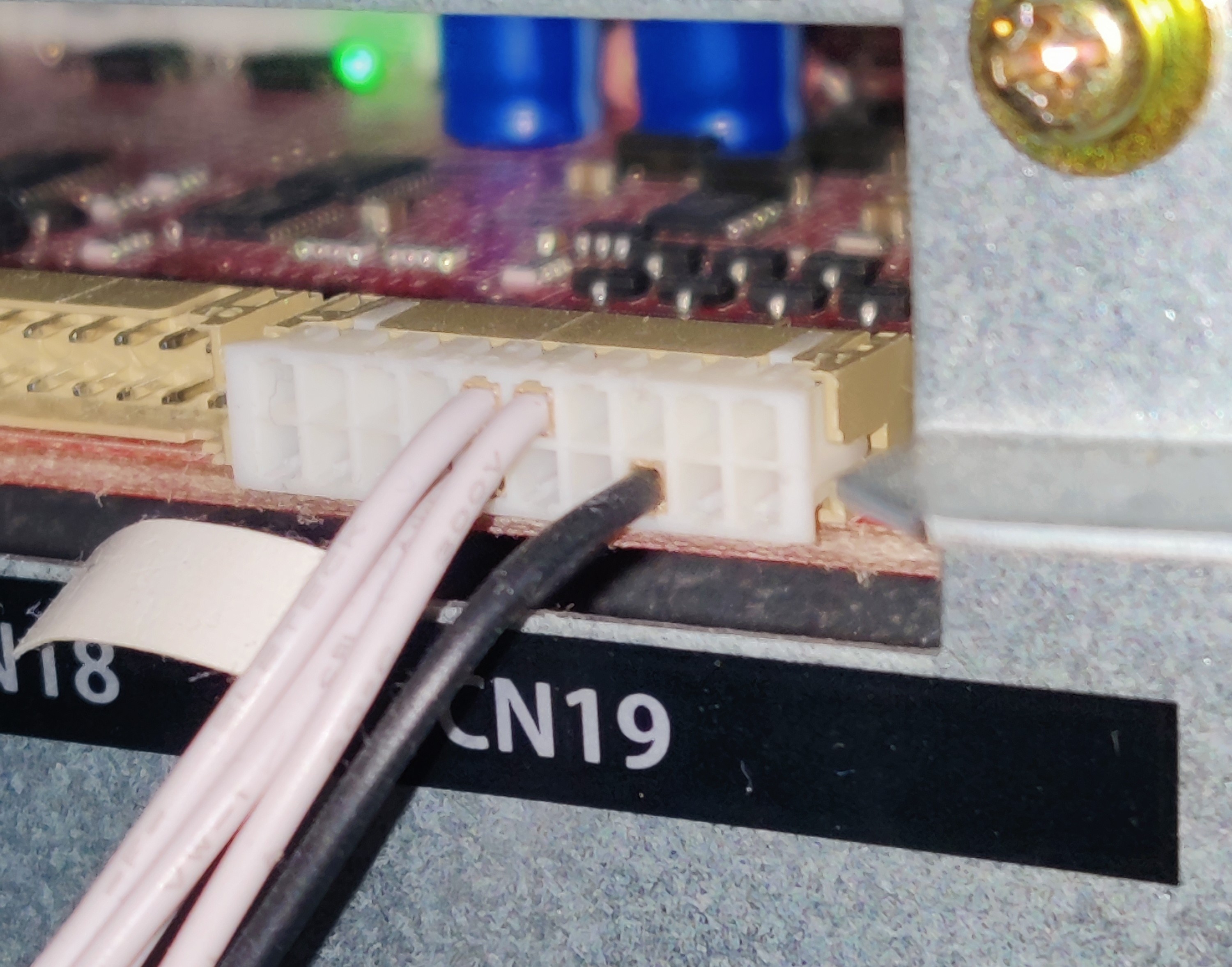
- CN19: TT Lights and Woofer Blue Light
Setting up for TDJ
For a Tricoro cab, luckily most of the hard work is done, so basically what you need is:
- A screen capable of displaying at least 1080p@120hz
- A touch screen capable of displaying 720p@60hz
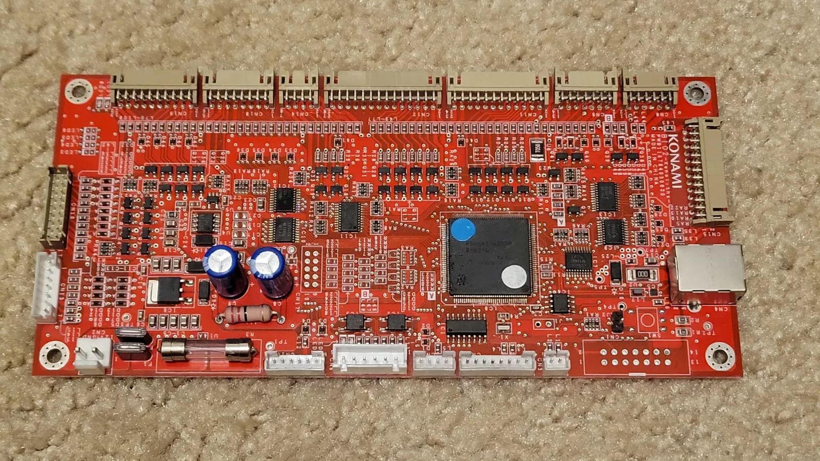
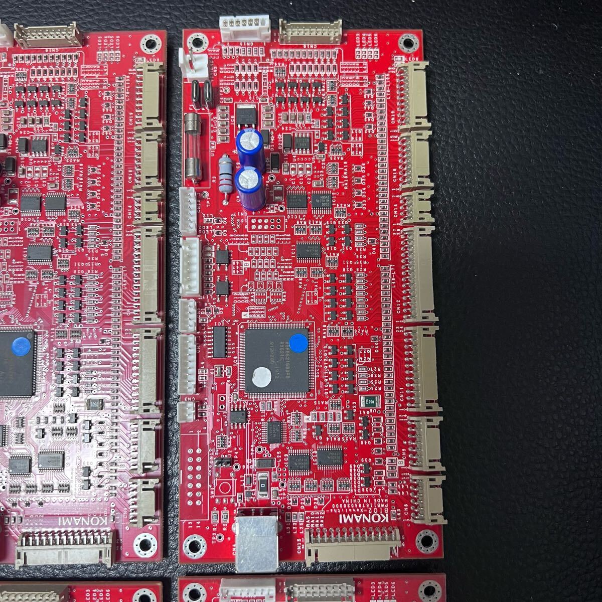
- BIO2 board with BI2X firmware
Other cabinet models will need ICCC readers (called “blue readers”) and a rewiring job for the readers to work. Tricoro cabs already have this set up.
You will also need to put back the original turntable teeth discs, or at least some discs that have 72 teeth instead of 144, and with it’s original mounts if you changed them for the same mod, since BI2X firmware reads half pulse, which results in having the same sensibility as having a 144 teeth disc on LDJ.
Instead of using the original aluminium discs I’ve used 3D printed discs. Design made by @roxandtol: https://www.printables.com/model/1525394-iidx-turntable-tooth-wheel
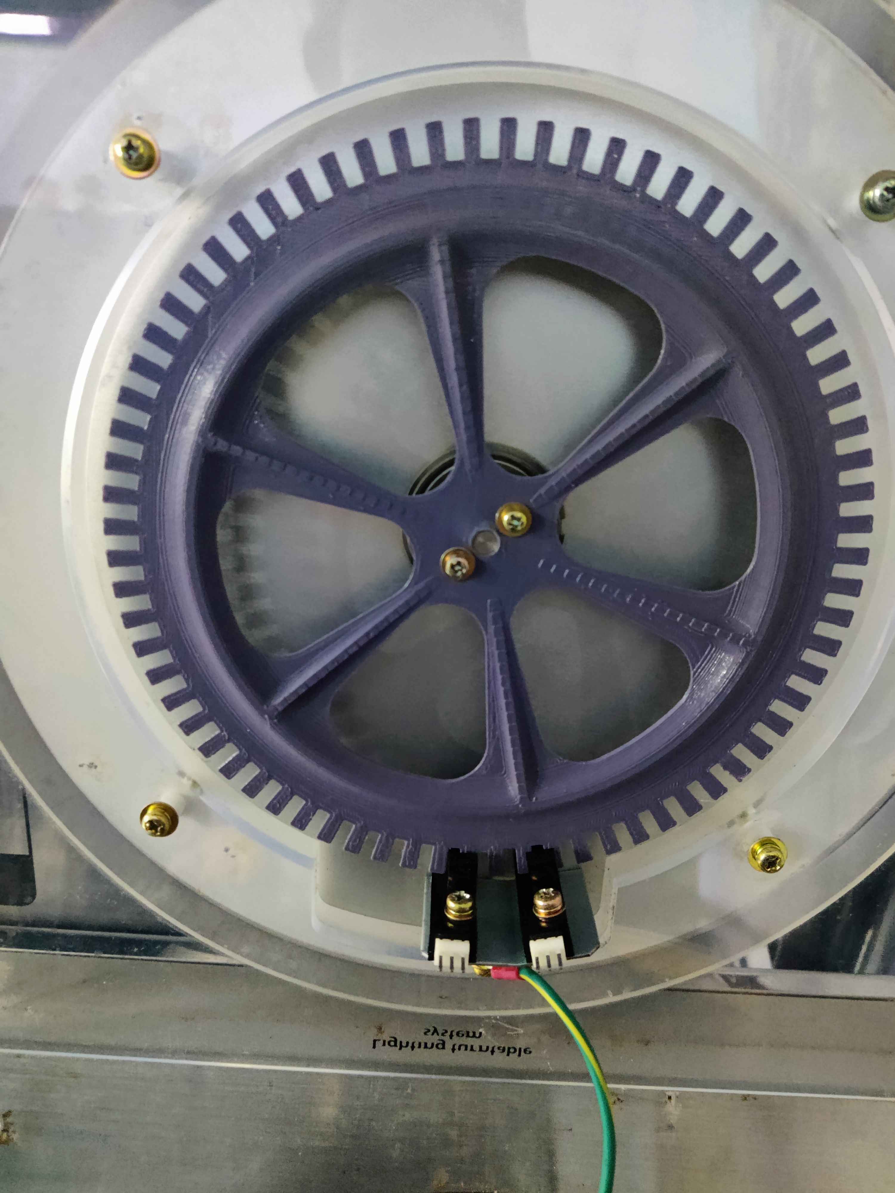 3D printed 72 teeth wheel
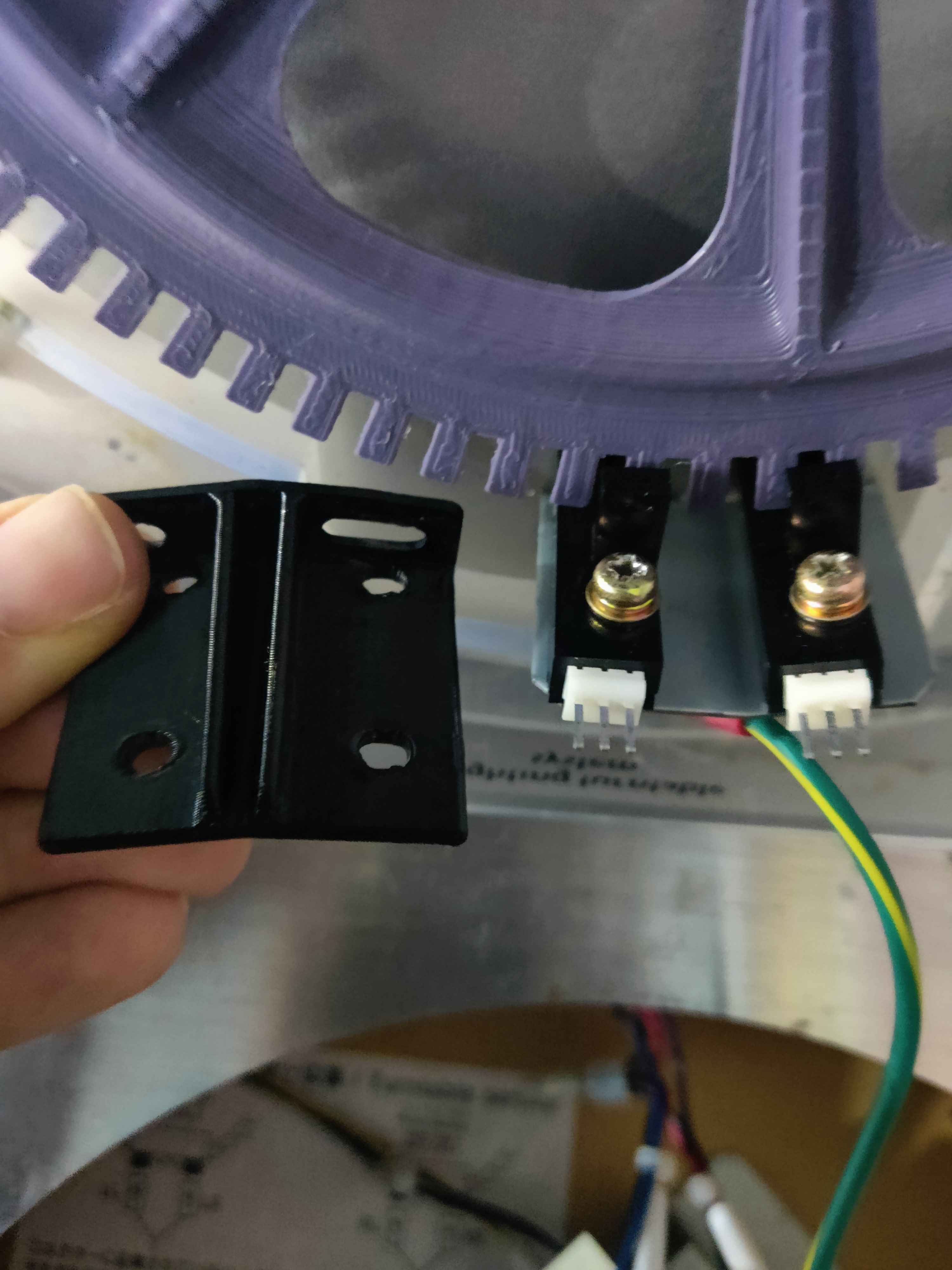 Comparing the mount for 144 teeth wheels to the original mount
TODO: insert more info for older cabinets
Screen
In my case I’ve used a LG C5 42” OLED TV, which is as big as the CANNON BALLERS screen. This TV in specific offers very low input lag too. LG OLED TVs, while usually expensive, are highly recommended. Cheaper options can be considered if looking instead for VA panels, like the Gigabyte AORUS FV43U.
Other options to consider for both VA and OLED are also screens from Sony, Samsung, Asus, LG QLED ones, etc.
Some more models can be found in iidx.org.
A cheaper option available in the US is to get a Vizio Quantun 43” display. In EU maybe some options might be either Hisense or TCL.
If you have an original Tricoro monitor with its mount, I recommend to take the entire mount and disassemble the monitor starting from below the mount.
Some people instead kept the monitor chassis by replacing only the monitor with an Asus ROG Swift PG38UQ 38” display, so it is an option to consider if you want to keep the original look.
The screen will be connected to the graphic’s card DisplayPort. If your screen only has HDMI input, like LG OLED’s screens, you might want to get a DP to HDMI converter dongle. I got this one for example: https://amzn.eu/d/0iVZCXwP
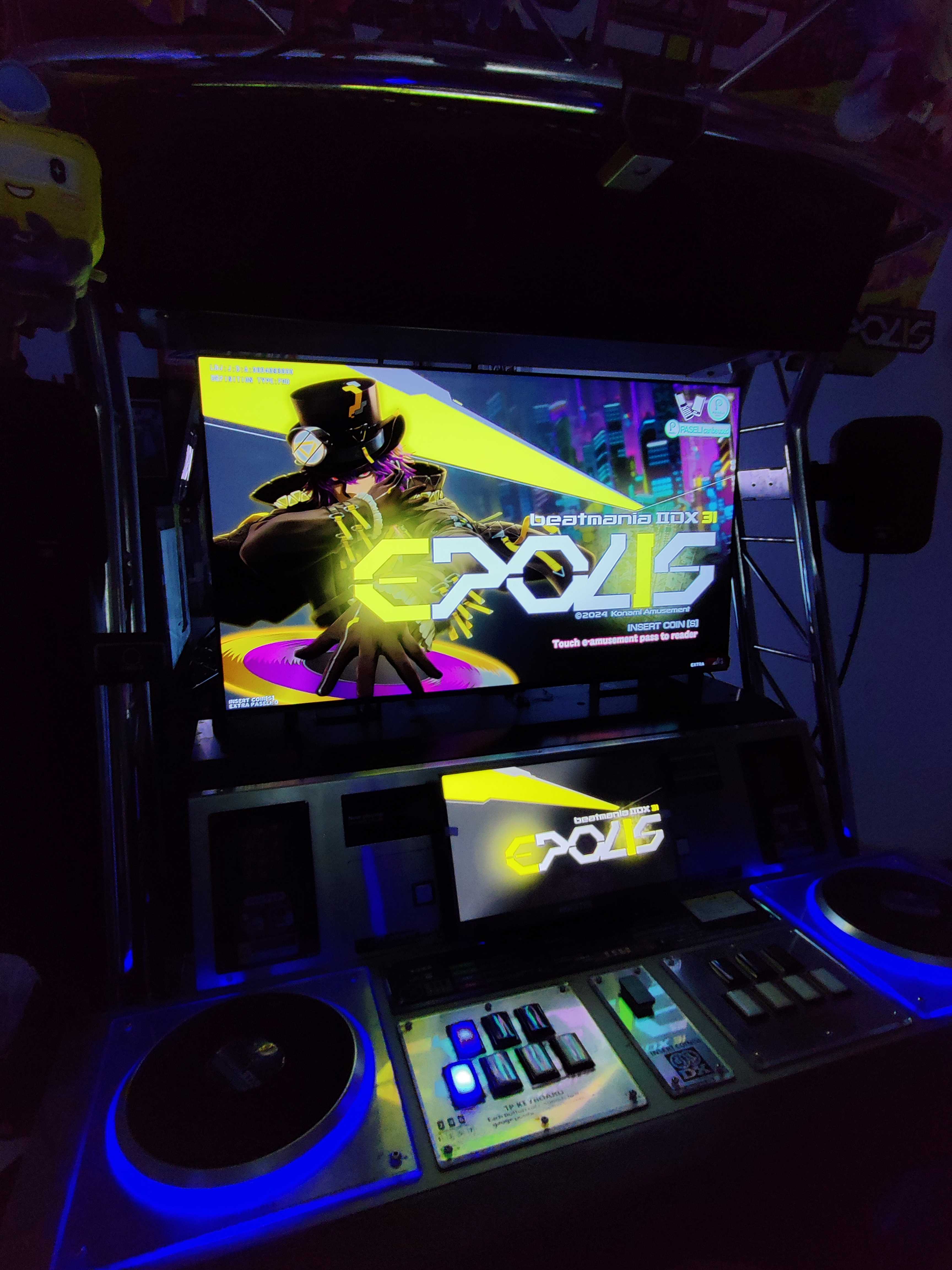 LG OLED C5 42” showing IIDX
Touch screen
Any touch screen that complies with the characteristics above should be enough. In my case I got this one from Aliexpress, as a cheaper option (or at least it was when I bought it): https://aliexpress.com/item/1005007445019329.html
FYI
You might need to buy longer cables than the ones provided with the screen itself, the cables included with the one I got weren’t longer than 1 meter at most.
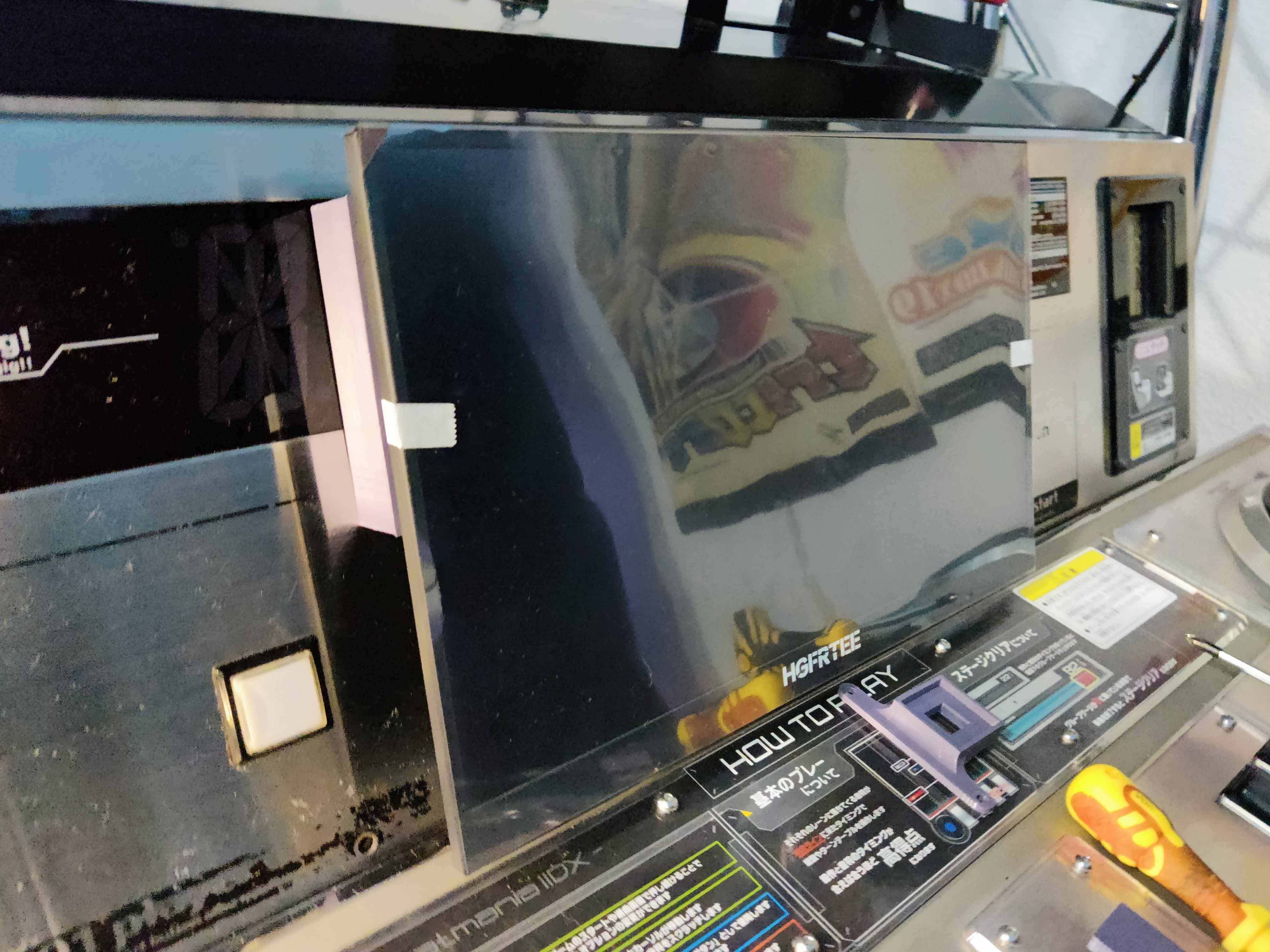
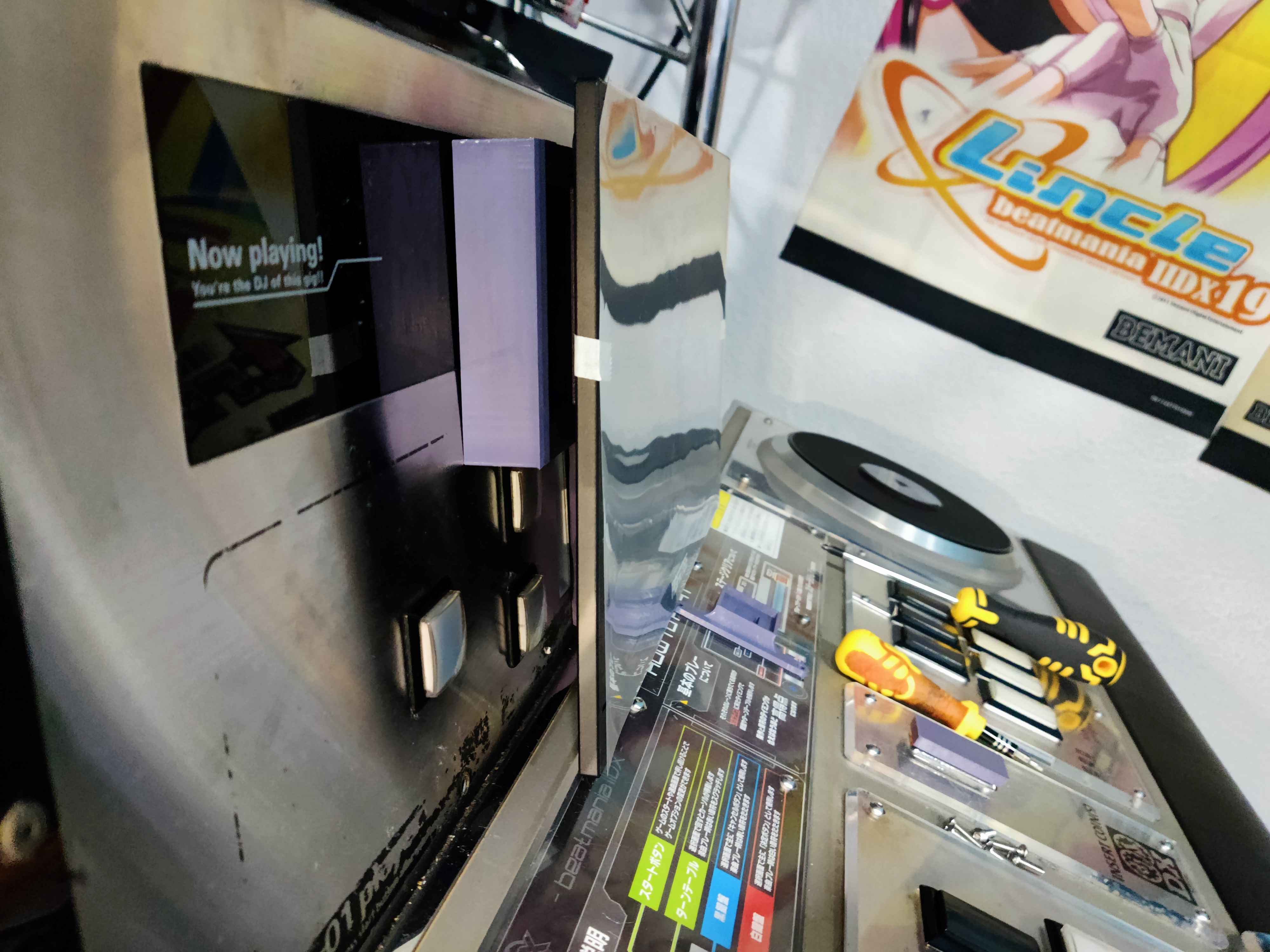
Additionaly a mount for the touch screen is ideal to keep it in place. I used the one made for this guide by @kursain: https://www.printables.com/model/1362898-beatmania-iidx-lightning-model-upgrade-parts/comments
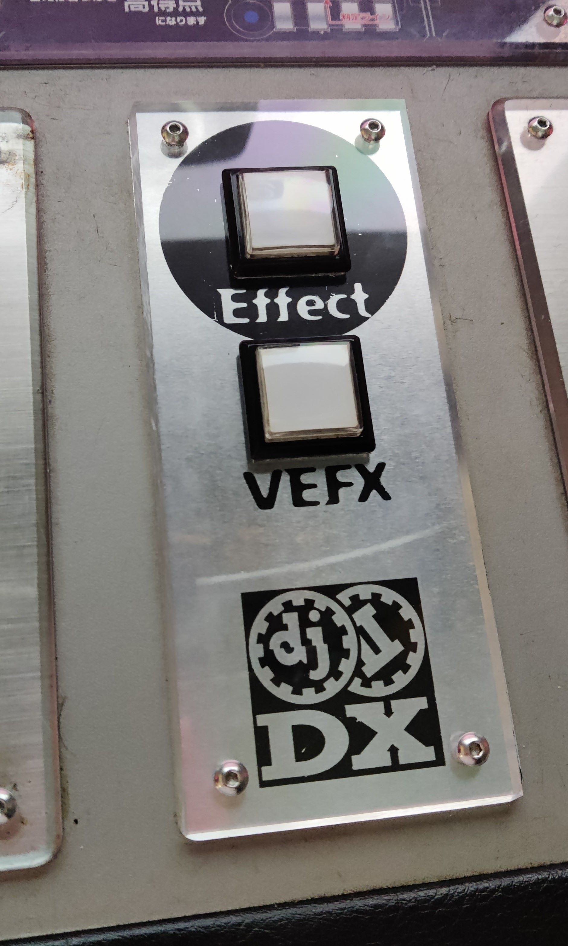
This mount sits over the sliders, hiding them completely, and it’s held from behind the front panel, having to remove the slider PCB previously, only downside is that it stays over the Effect and VEFX buttons. The same guide also provides a printable model for replacing the Insert Coin plate with a piece which holds both buttons.
TODO: add pictures for coin insert plate with effect and vefx buttons
The subscreen will be connected to the graphic’s card first HDMI (labelled HDMI 1) and at least one USB C for touch input into the PCB USBs
Buttons
Since the subscreen, as set according to the previous section, will be blocking the Effect and VEFX buttons, a good idea would be to move said buttons to the Insert Coin plate like in Kursain’s guide.
In my case, I took a different approach, instead of using his printed models, I opted for using an acrylic piece and aluminium plate like the original Insert Coin plate, which I think it fits more with the overall look. The models and art used for the new Insert Coin plate are made by @dj_shoko and can be found in the Rhythm Game Cabs discord.
For this you will need to make an extension harness with fastons terminals for both the connectors that come from the cab and the switches. Making these cables and running them is a pretty straight-forward job. The coin section is accessible through behind the front panel and shoving your hand by the center of the deck.
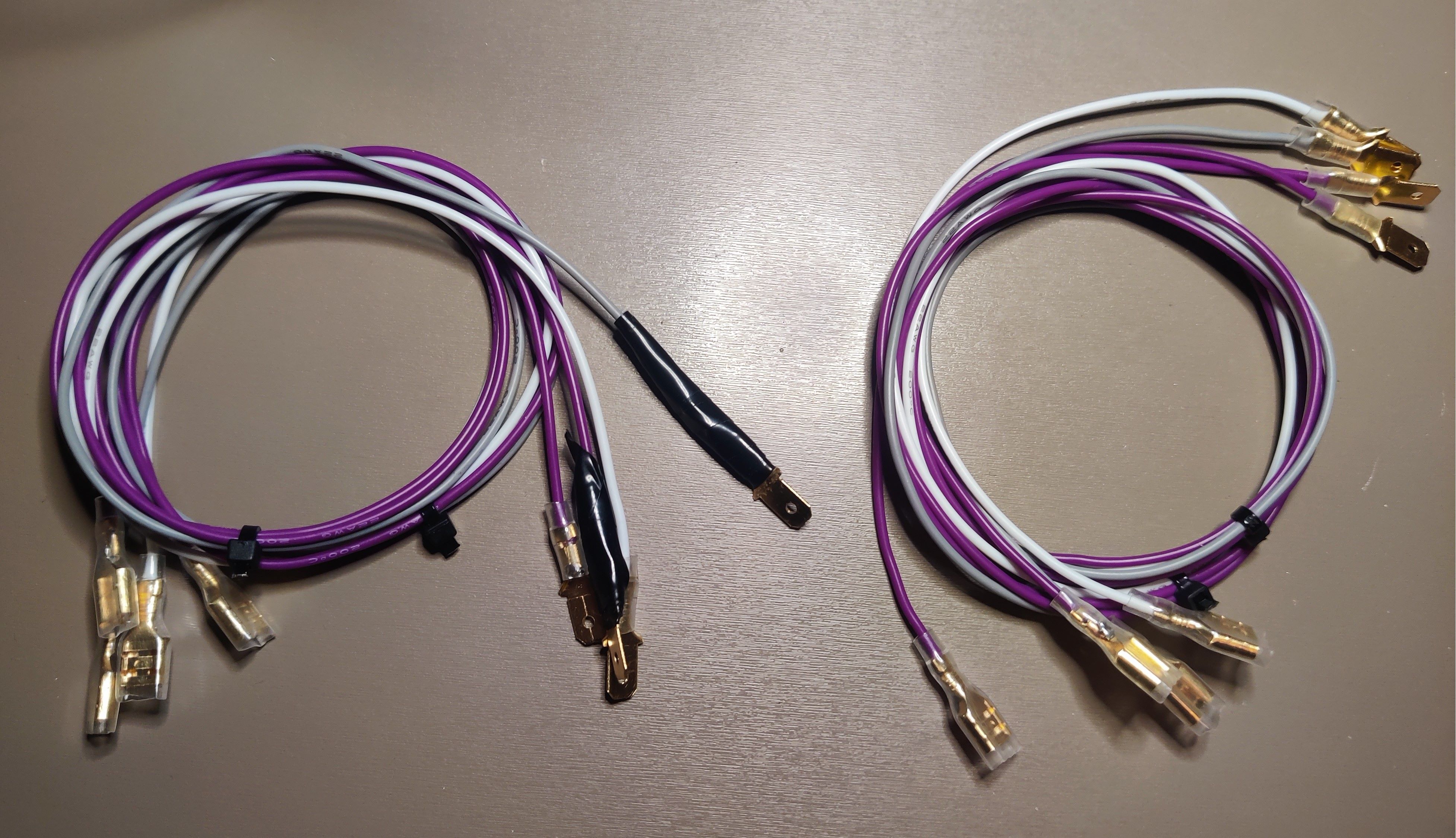
 Insert Coin plate with custom art and holes for the Effect and VEFX buttons
TODO: setup for LM-like start buttons
BIO2
If you got a CCJ for the upgrade needed to run EPOLIS, then you may have a spare BIO2 with BI2X already flashed, otherwise you may have to flash your BIO2.
How do you know if you have the correct one? On Windows, when connecting the board to a PC, you can check its PID on the Device Manager, if the PID is 8050, then it’s good to go, otherwise if it’s 8040/804C, then it still has BI2A firmware.
On first boot you may get a USB I/O ERROR: EROR BI2A message, which probably may depend on setup, but for me after a reboot the game loaded just fine.
If you got all of this done and it Works™, congrats, you converted your IIDX to a Lightning Model! You don’t really need anything else.
Only drawbacks for this convert is that top speaker lights and volume sliders go unused due to BI2X firmware. If you want the sliders to work then you may look for another solution instead of this, like 🏳️⚧️LDJ.
If you want the lights back and also working like in LM, then next up is how I managed to get them done, having working TT lights, woofer lights, reader lights, working audio jacks for headphones and an attempt to replicate the lights that can be controlled from the touch screen.
🎧 Audio Jack wiring
Audio Jack wiring
TODO
- Add pictures with headphone amplifiers
This section contains all related documentation, notes and results related the process of setting up headphone jack connectors on a Tricoro cabinet, in order to make it work like a LM cabinet, while making use of the BIO2 dedicated connections that are already programmed for these purpose on LM cabinets.
Planning
- Get same harness for CN15 (PHDR-26VS) and build to XMR-8V harness, the existing cable for 1P keys (BI2A wiring) can be reused
- Short to ground both HP and REC pins to have headphones always enabled
- Alternatively build some audio jack cables, using the mic pin for HP DETECT
- Either way headphone amplifiers will be needed.
- Given previous points, rewiring shouldn’t be needed
Audio Jack wiring outline
Alternative outline with audio cables

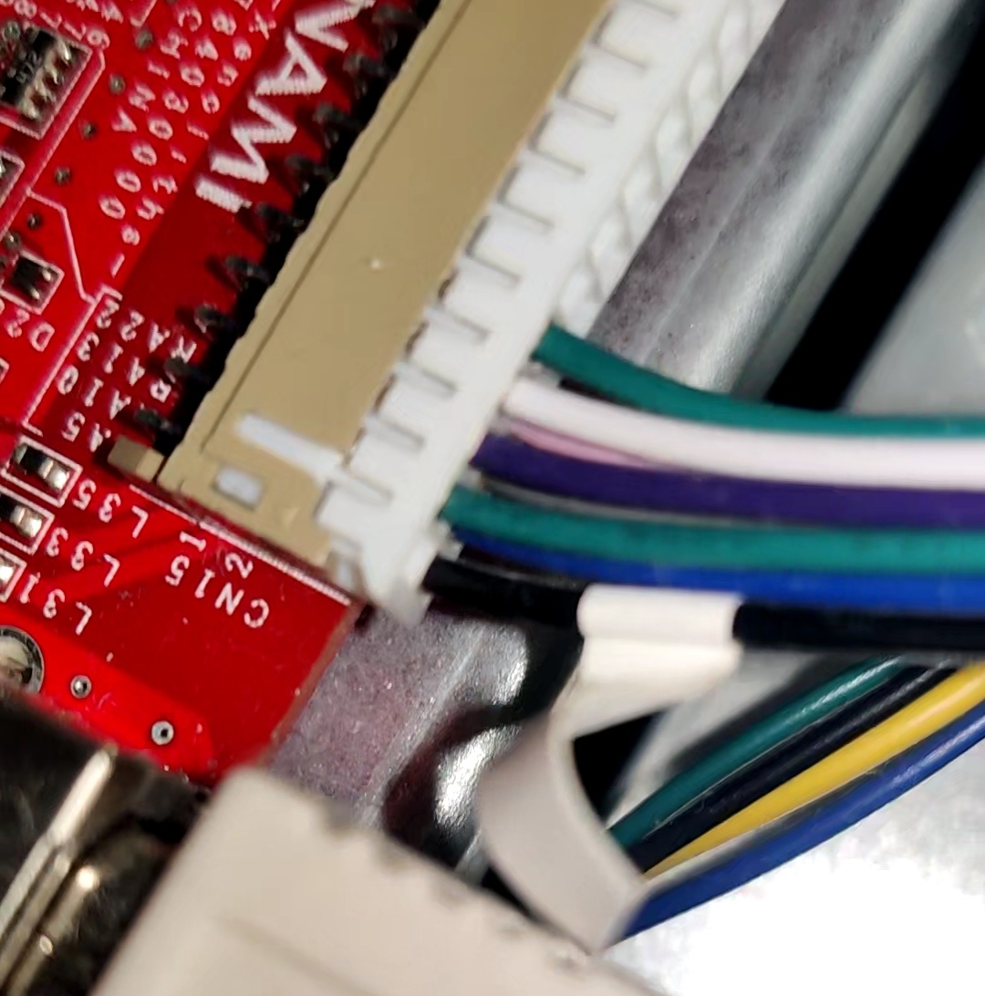
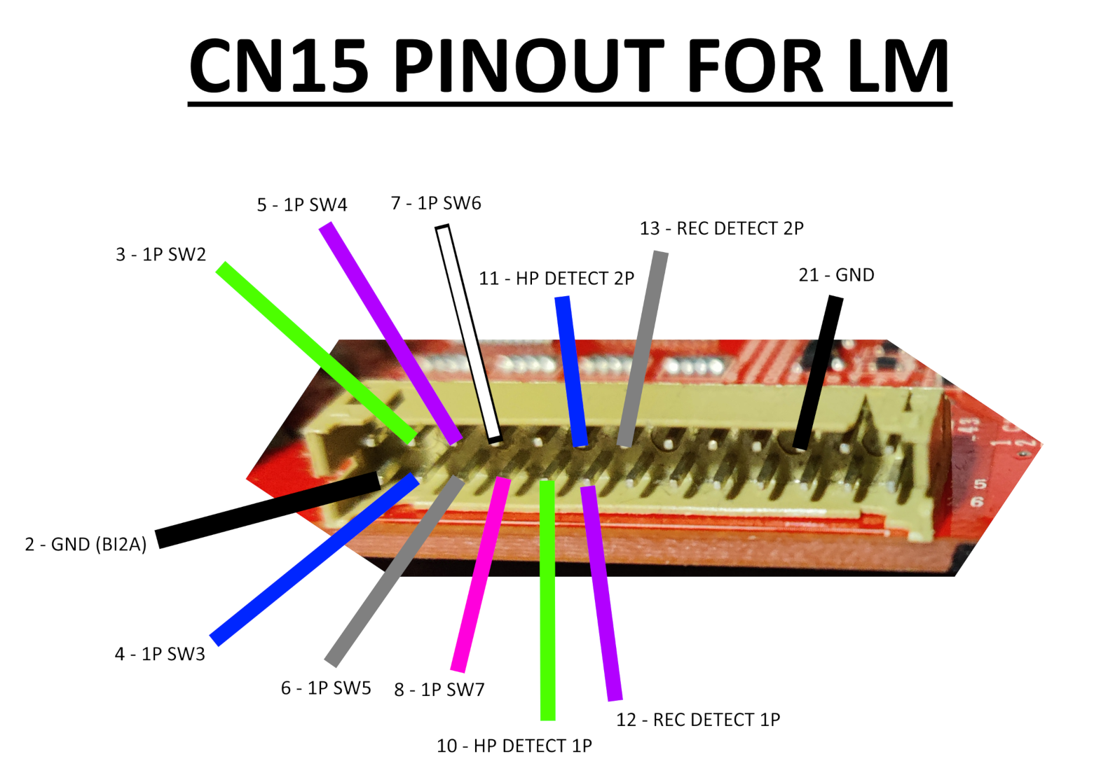
CN15
Bill Of Materials
If any link stops working, just try to searching for the piece in specific for the time being, you’ll probably find it.
PCB connector:
- PHDR-26VS:
- Harness: https://es.aliexpress.com/item/1005008107323180.html
- Terminals (SPHD-001T-P0.5): https://es.aliexpress.com/item/1005003975795283.html
Other end of cable:
- XMR-08V:
- Connector and terminals: https://es.aliexpress.com/item/1005009346695309.html
- Terminals (SXM-001T-P0.6): https://es.aliexpress.com/item/1005008545862370.html
Audio cable:
- TRRS 3.5mm female jack plug: https://es.aliexpress.com/item/1005008150971423.html
- TRS 3.5mm male jack plug: https://es.aliexpress.com/item/1005005672946991.html
- Sheathed wire (4 cores): https://es.aliexpress.com/item/1005007924124268.html
- Headphone amplifiers
- MAX4410 board: https://es.aliexpress.com/item/1005006230596608.html
- XH JST kit: https://es.aliexpress.com/item/1005006847308001.html
- DC input connector 2.1mmx5.5mm: https://es.aliexpress.com/item/1005007870346260.html
- HA400 amp (knock-off): https://es.aliexpress.com/item/1005006614134556.html
BI2A wiring
BI2X wiring
Headphones wiring

CN15 is the easiest one since it could be left as it is, but if you want headphones to work you need to add a few more cables (check BI2X wiring). From here you have two options:
- Short all HP and REC DETECT pins to GND, REC DETECT pins may be just left unused (diagram)
- Build headphone cables that mainly goes to the audio card, with an extra cable soldered to the mic pin of the jack that goes to each HP DETECT pin on CN15 (diagram)
The first option is more of a shim than anything, but it lets you setup headphone volume through the touch screen since this makes the game believe that both headphones are connected.
The second solution ensures that the headphones will work since the game will detect that they have been plugged to either 1P or 2P jack and will let you change headphone volume through the volume settings in the touch screen.
XONAR ports
First thing to take into account is that the respective outputs for each player on the XONAR are as it follows, from start to bottom:
- P1: SIDE output (last port)
- P2: REAR OUTPUT (4th port)
For the audio cables, I’ve made them with a length of ~180cm (shorter than I would like, 200cm may be better) and soldering TRRS/4-pole female jack plugs with TRS/3-pole male jack plugs, leaving the mic pin from the female jack separated for crimping and inserting it in their respective HP DETECT pin. (References can be seen here and here)
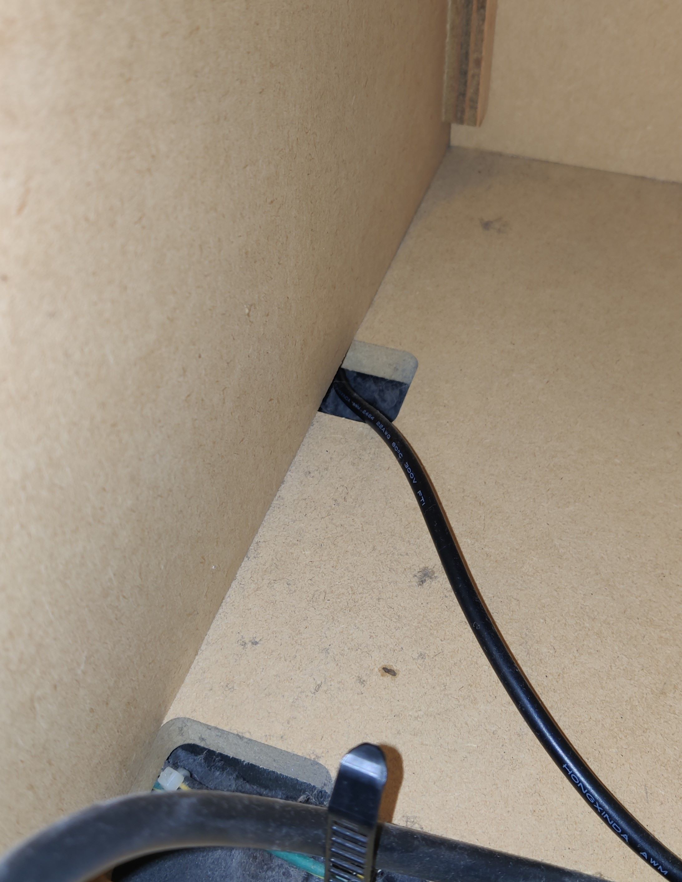
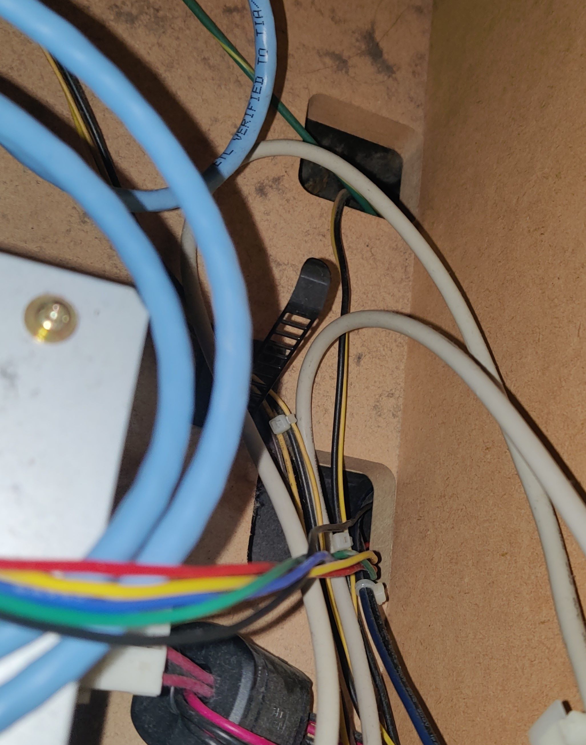
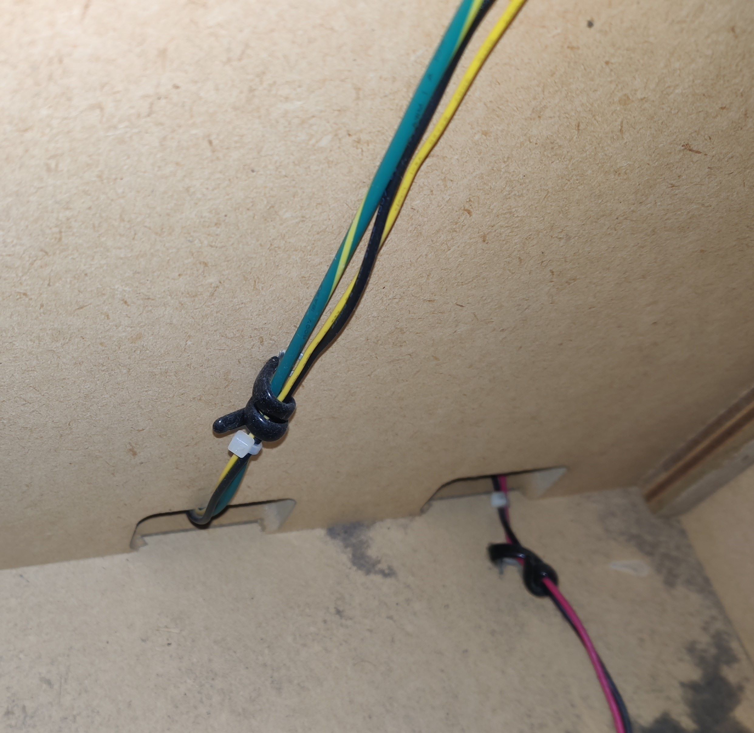
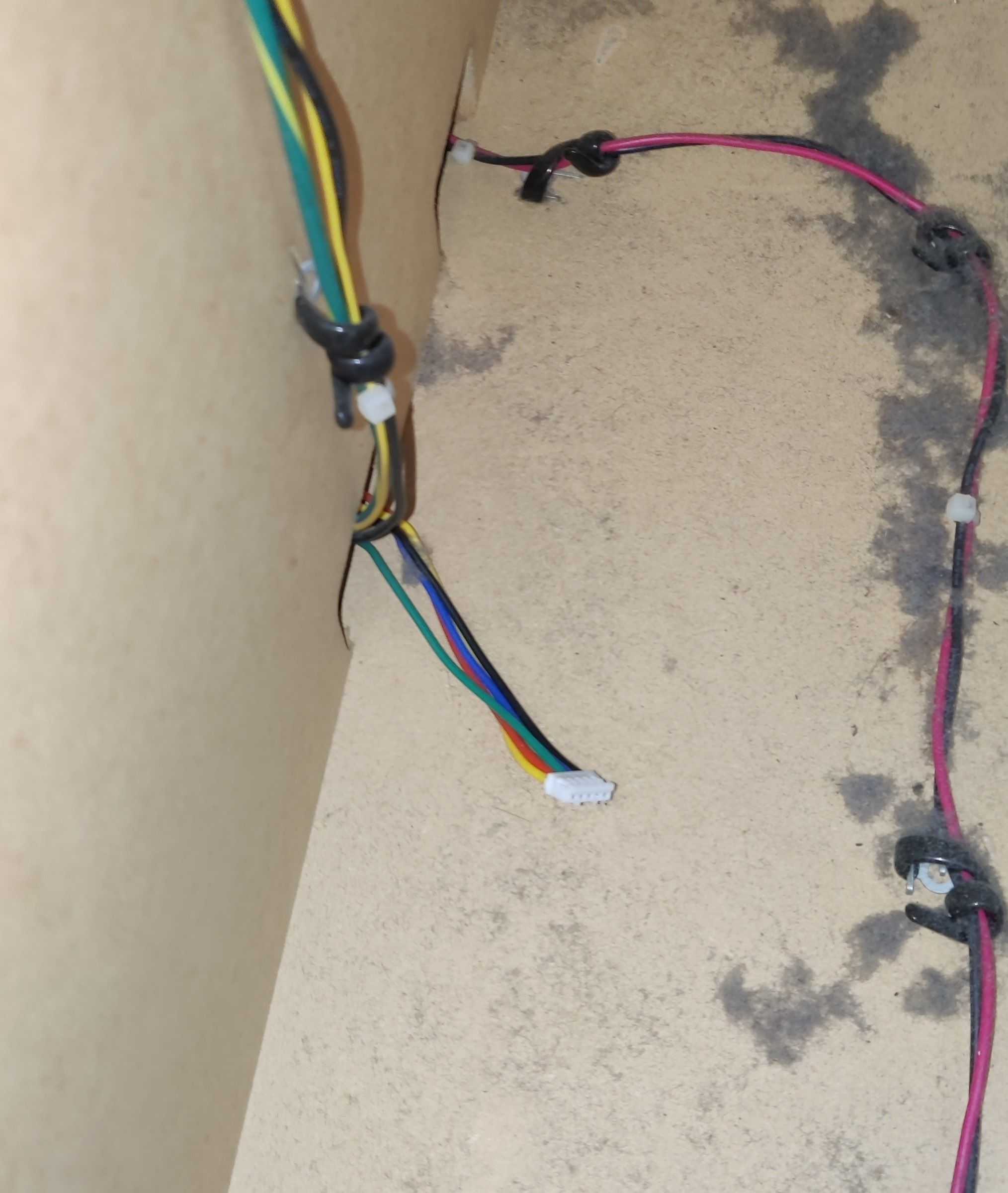
The audio cables can be taken outside through some holes that can be found inside the cabinet, you can see that through some of them the wires for the woofer speakers and woofer LED lights are being passed through, I used the one that is further away (third hole) which also connects directly outside unlike the other ones, which are covered with a metal plate.
Audio cable being passed through the farthest of the holes, the nearest two carry wires for the woofer speaker and the woofer LEDs respectively
Audio cable outside the cabinet. Metal plate that covers the other cables can be seen in the back
At this point the headphone functionality should be working right away, the only detail left is that the audio by itself will be very low, so you will need an amplifier for both channels. Demonstration of headphone detect functionality working, before adding amplifiers (the highlighting of the volume control isn’t really appreciated in the video)
Following the diagrams of an LM cab, assuming the headphone amplifier and headphone jack PCBs are the same as Sound Voltex Valkyrie cabs (or at least Nemsys cabs since they would have very similar components as these two if not the same), the amp handles the signal coming SENS pin and then signals JACK DETECT (HP DETECT on BIO2’s CN15) and REC DETECT (same name on BIO2) depending on the connected device, and also all grounds in the amp are merged (reflected in this diagram)
Behringer HA400 amps work really well and can be very cheap. You may also get MAX4410 amp boards instead if you want an even cheaper option with the trade-off of having to build the necessary components yourself.
Only caveat with these amps is the grounds and how they are merged, HA400 amps have them merged only for the audio input and DC input, not the audio output, which means that you may have to join the grounds of the input and output jacks (if you’re also building the cables like I did)
TODO: TO BE TESTED
MAX4410 amp boards in the other hand do have all its grounds merged, which may be the most straight-forward solution with only having to setup the cables in that regard.
TODO: TO BE TESTED
For the record, the headphone detect functionality works without any amplifier in the middle of the setup (i.e. conecting these cablesas they are), which points to the minimal condition for it to work being that at least the ground continuity should not be cut at any point in between the headphone jack and the XONAR port path.
The audio plugs are positioned just below the deck, trying to keep them under the player buttons like in a Lightning Model cabinet, and to keep it fancy (and secured) a little 3D printed bracket was set up, made by @roxandtol: https://www.printables.com/model/1624880-pj392a-bracket-for-iidx
These brackets are attached using the M5 screws that you can find below the deck. You can see references here and here
Results
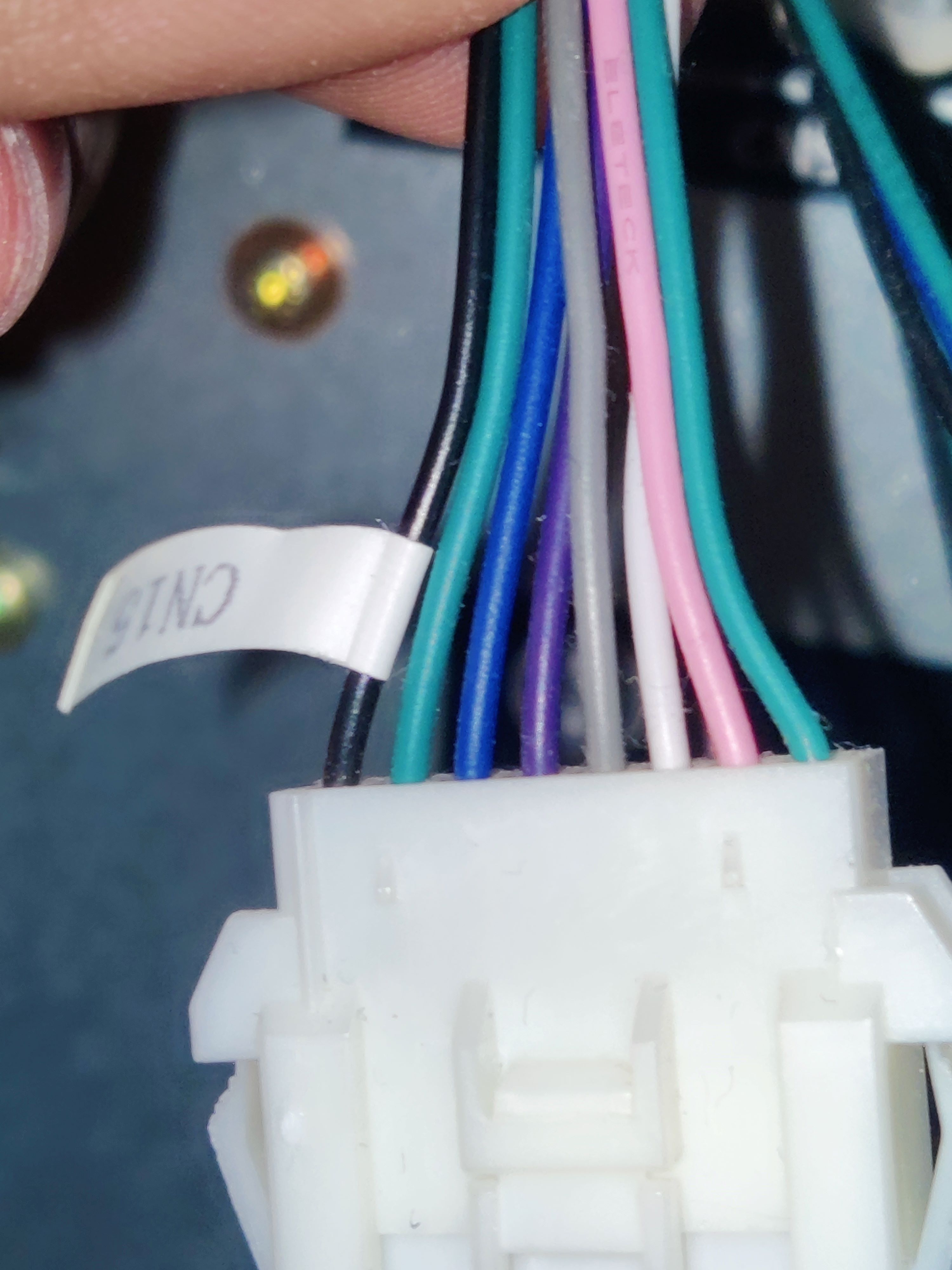
CN15 connector for legacy harness
New CN15 harness with HP DETECT and REC DETECT shorted to ground
Audio cables with microphone pins crimped for CN15
CN15 with HP DETECT pins (last two white wires), coming from the audio cables
Audio jack with 3D printed bracket
Link to original
Audio jack with 3D printed bracket from below, using one of the screws from below the deck


🚥 RGB Lights wiring
RGB Lights wiring
WIP
- Reader LEDs not installed
TODO
- Add results for reader LEDs
Proceed with Caution
Careful when making the harnesses for this part
You will need at least 24 AWG wire for most connections, specially for feeding +12V to the LEDs, and also keep the same gauge size for grounds. Wires that carry signals should be fine with smaller gauge.
In my case I did everything with 22 AWG just to be safe. In the list below you can find already built harnesses for the needed connectors, although some may differ from what I used.
Bill Of Materials
If any link stops working, just try to searching for the piece in specific for the time being, you’ll probably find it.
DC OUT (for feeding the LEDs):
- VLP-04V
- Connector and terminals: https://es.aliexpress.com/item/1005009428438124.html
- Alternatively, draw 12V directly from PSU by plugging some molex
- https://es.aliexpress.com/item/1005006026259742.html
CN10 (reader and woofer LEDs):
- XADRP-18V → XADR-12V
- XADRP-18V:
- 22 AWG Harness: https://es.aliexpress.com/item/1005009404019959.html
- Connector only: https://es.aliexpress.com/item/1005007898440466.html
- Terminals (SXA-001T-P0.6): https://es.aliexpress.com/item/1005004425152785.html
- XADR-12V:
- Connector: https://es.aliexpress.com/item/1005008366405192.html
- Terminals (SXAM-001T-P0.6): https://es.aliexpress.com/item/1005008545737745.html
CN19 (woofer blue light, turntable LEDs and turntable sensor):
- PHDR-20VS:
- 22 AWG harness: https://es.aliexpress.com/item/1005008082796097.html
- 24 AWG harness: https://es.aliexpress.com/item/1005009363053705.html
- Connector: https://es.aliexpress.com/item/1005008735680501.html
- Terminals (SPHD-001T-P0.5): https://es.aliexpress.com/item/1005003975795283.html
- Socket (plug doesn’t exist) - B20B-PHDSS:
- https://es.aliexpress.com/item/1005008318489480.html
- 26 AWG harness to PHDR-20VS (2x10P): https://es.aliexpress.com/item/1005005572943124.html
IC/W LED connector:
- XADR-12V → XADRP-12V
- XADRP-12V:
- 22 AWG Harness: https://es.aliexpress.com/item/1005009492628988.html
- Connector: https://es.aliexpress.com/item/1005008376807266.html
- Terminals (SXA-001T-P0.6): https://es.aliexpress.com/item/1005004425152785.html
- Woofer connector:
- XMP-05V → XMR-05V
- XMR-05V:
- Connector (terminals included): https://es.aliexpress.com/item/1005009346695309.html
- Terminals (SXM-001T-P0.6): https://es.aliexpress.com/item/1005008545862370.html
- XMP-05V:
- Connector: https://es.aliexpress.com/item/1005005678537487.html
- Terminals (SXA-001T-P0.6): https://es.aliexpress.com/item/1005004425152785.html
- Reader connector: PHR-5
- Directly into RGB light, lights are independent from reader signal
LED PCB connector:
- PHR-5
- 22 AWG Harness: https://es.aliexpress.com/item/1005009702800874.html
- Description says it’s 22 AWG, however the product itself was 24 AWG
- Connector and terminals: https://es.aliexpress.com/item/1005007441813591.html
- At least one for each pair of LEDs, since they are connected in series:
- 2 LED PCB per turntable + 1 cable for incoming data = 2 cables per TT
- 2 LED PCB per woofer + 1 cable for incoming data = 2 cables per woofer
- 1 LED PCB per reader = 1 cable per reader
- Total = 10 cables
RGB strip for missing lights:
This section contains all related documentation, notes and results related the process of setting up existing LED lights in a Tricoro cabinet to behave like the lights of a LM cabinet, while making use of the BIO2 dedicated connections that are already programmed for this purpose on LM cabinets.
DC OUT
According to the manual, all grounds are merged to the PSU’s ground, therefore you can use the DC OUT connection which the cable itself is an extension of the PSU’s molex. Alternatively you may use a molex cable and splice 12V and GND from it.
RGB Lights wiring outline
Planning
- According to LM’s manual, both +12V and GND are taken from DC OUT (PCB’s PSU), meaning that all related grounds to RGB LEDs close the circuit in the same ground would need to be connected to the BIO2 and finally the PSU, since the BIO2 also feeds from the PSU. This would be:
- TT LED colors
- Woofer LED colors
- Reader LED colors
- All LEDs GND pins
- Reader LEDs current and ground however might need to be taken from COM1, at least for the ground since +12V comes directly from PSU, ground is taken from PCB’s serial
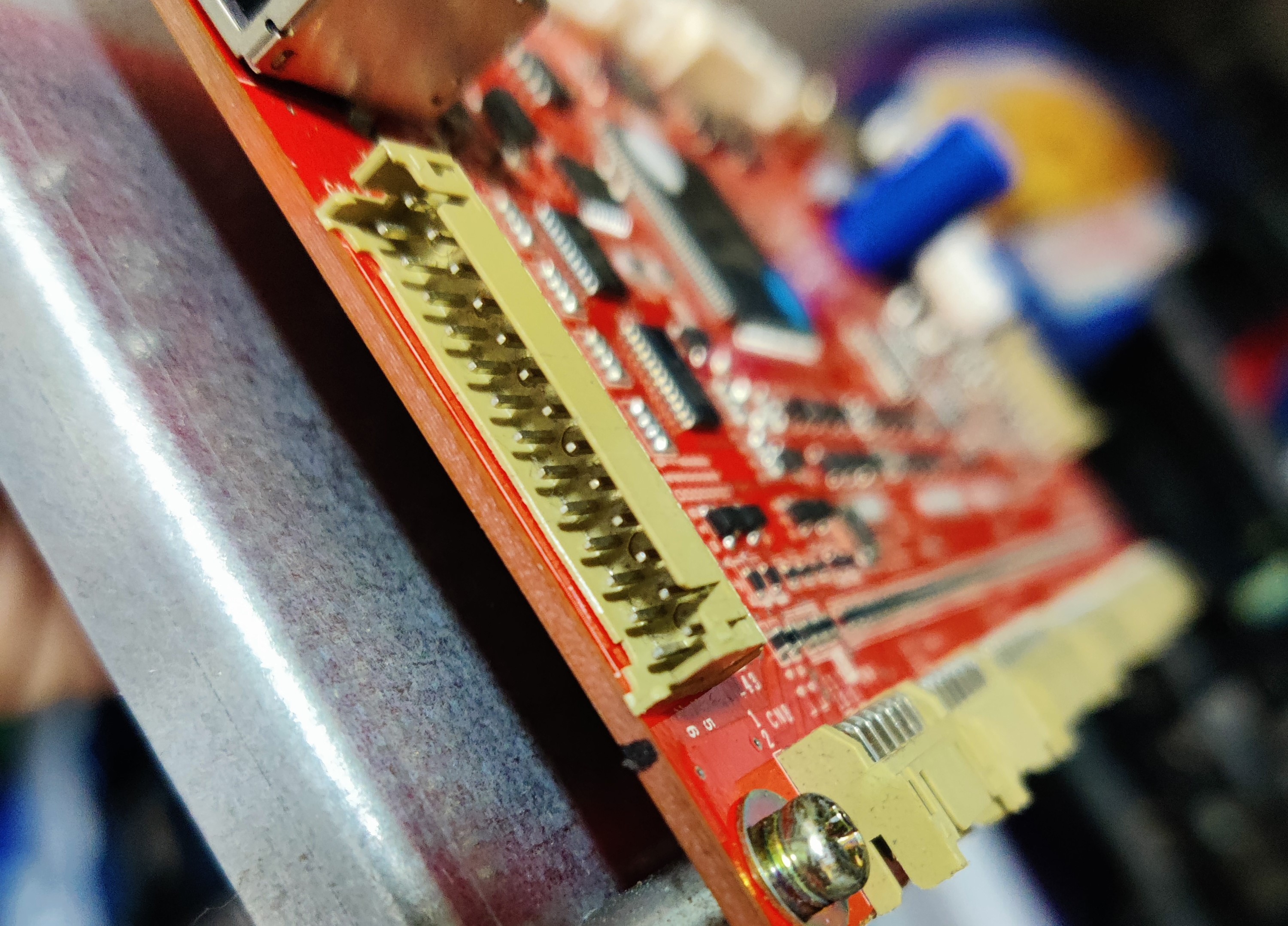
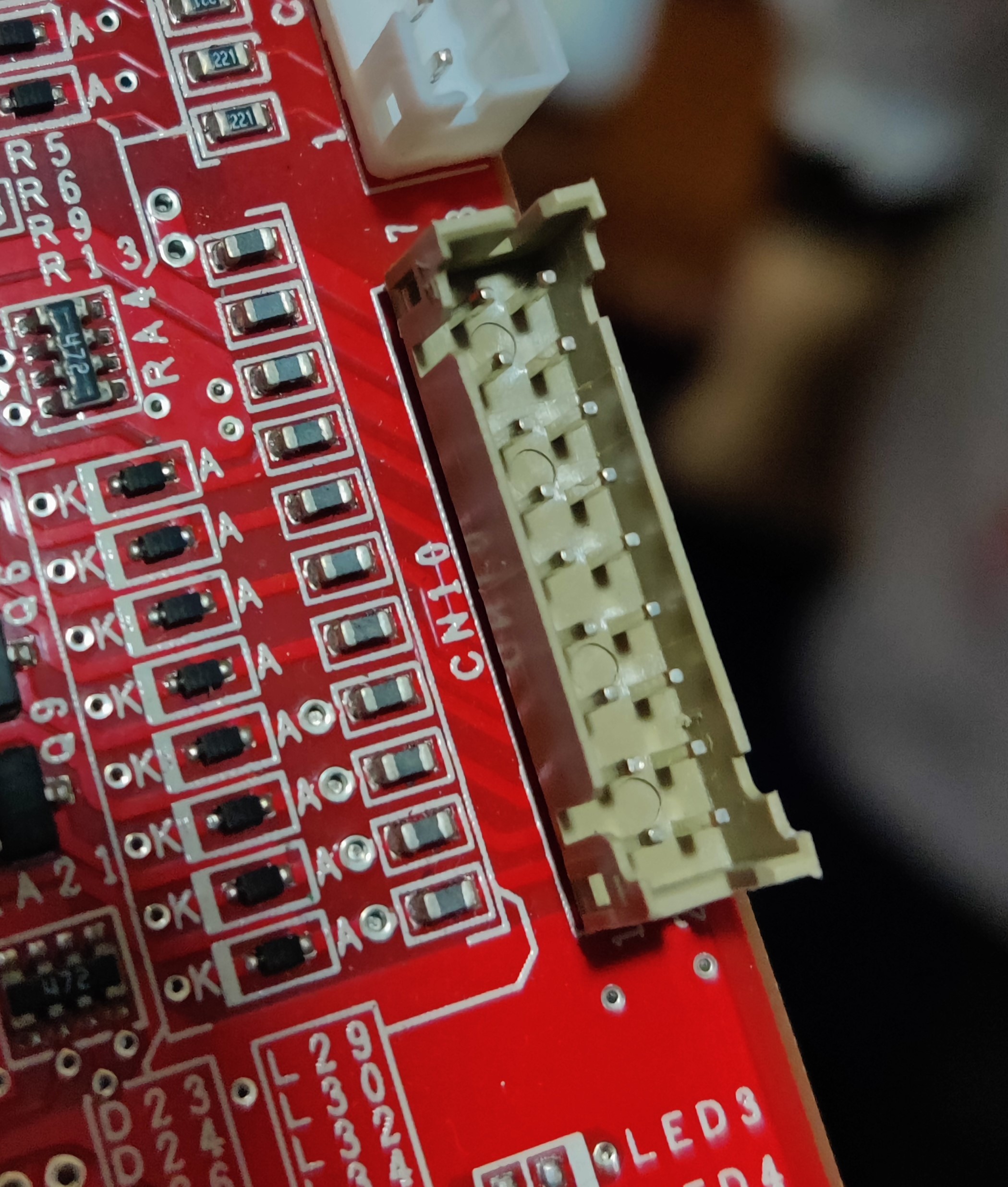
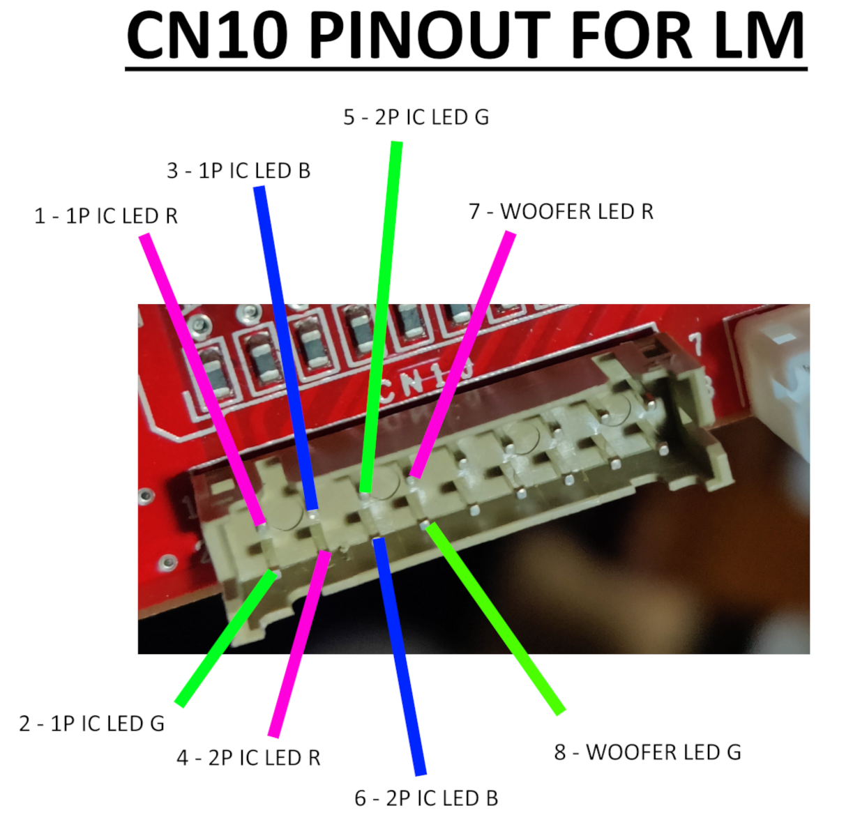
CN10
CN10 only carries color signal for both reader LEDs and red and green for woofers. Blue color for woofers is found at the first pin of CN19
Cable length should be atleast the following:
- Reader LEDs: ~80cm
- Woofer LEDs: ~180cm each, 200cm max.
- LED bridge cable length: 15cm
Following the main outline the relay board is completely ignored and cables go directly to the LED boards.
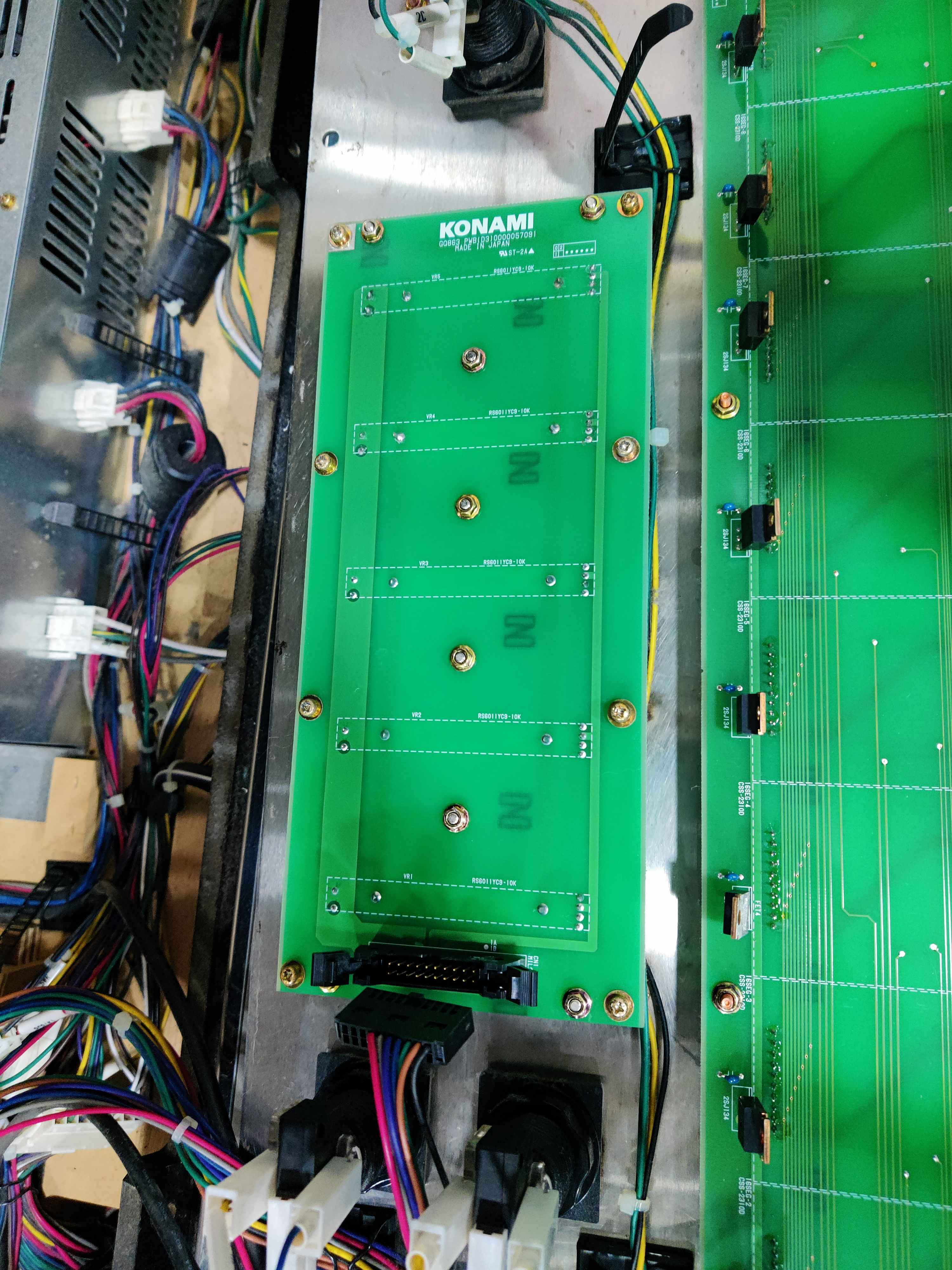
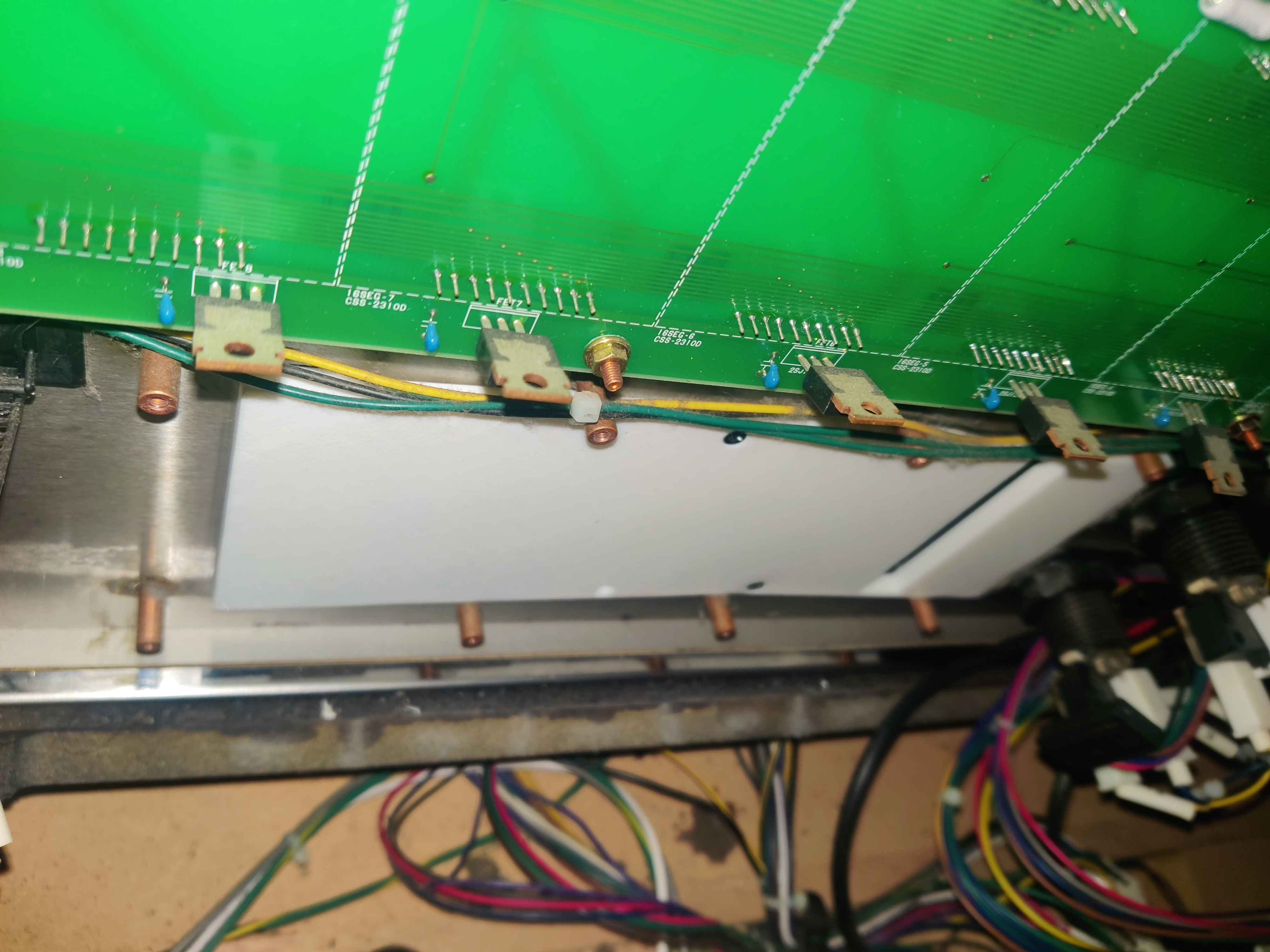
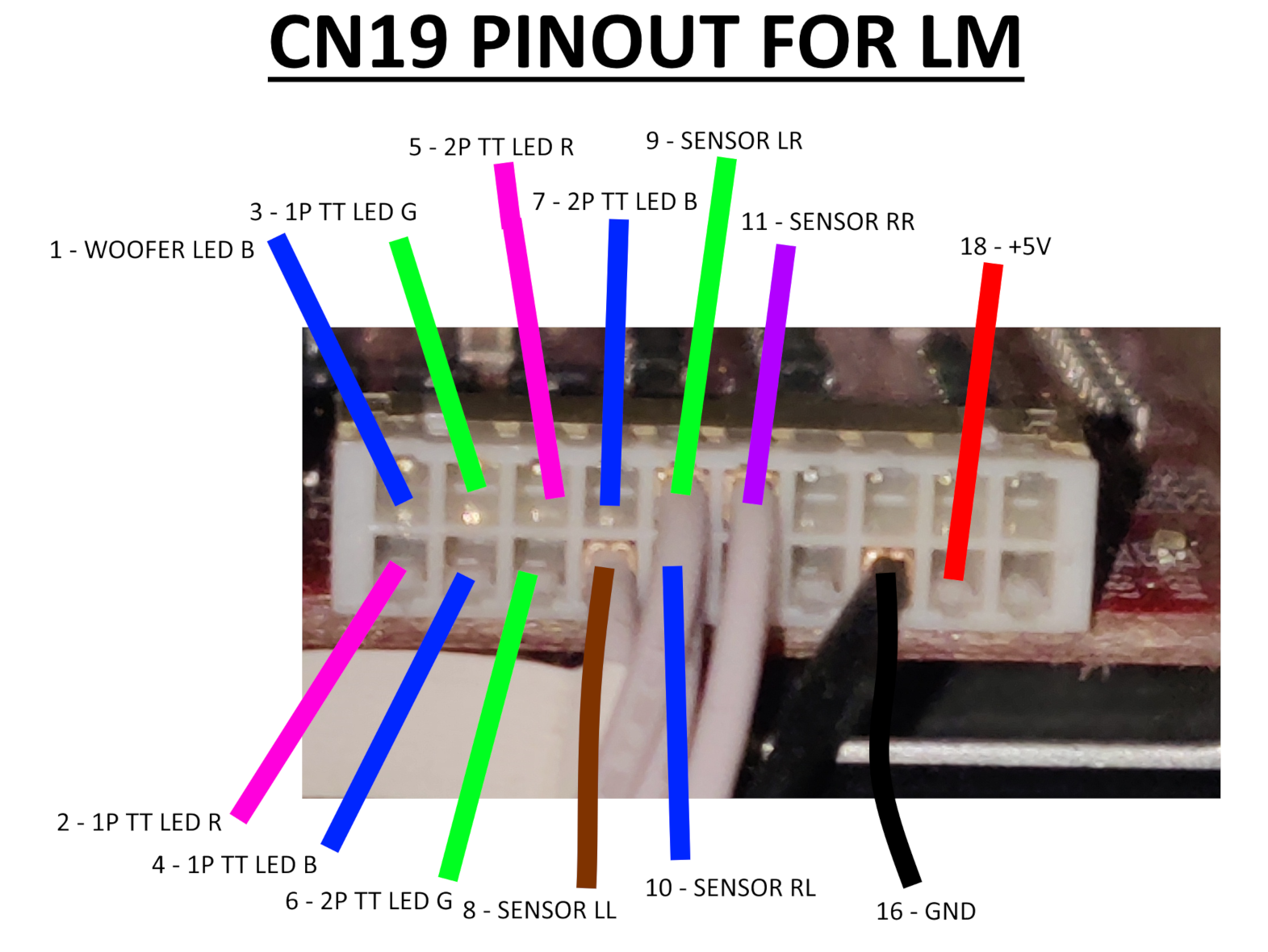
CN19
CN19 will be essentially the same as the pinout for BI2A: TT sensor signal and ground are on the same pins, while the rest are used for TT LED color signal. The +5V at pin 18 are used for TT photosensors but they already get fed so no need to rewire.
BI2A pinout
BI2X pinout

For TT sensor wires I soldered the necessary wires to a board socket connector, B20B-PHDSS, that pairs the PHDR-20VS, this choice is due to no plug connector existing so I had to approach it differently, but it works™ nonetheless.
Woofer LED B wire (pin 1) goes to IC/W LED cable, which bundles color signal wires for woofers and reader LEDs.
Cable length should be atleast the following:
- Turntable LEDs: ~150cm
- LED bridge cable length: 15cm
Following the main outline the relay board is completely ignored and cables go directly to the LED boards.
Woofers
- Woofer RGB connector: XMP-05V → XMR-05V
- LED PCB connnector: PHR-5
- LED bridge cable length: 15cm
- Cable length: ~180cm each, 200cm max.
- From last-end connector to LED PCB
Check CN10 very carefully
Apparently the connector for CN10 on the outer side of a CCJ PCB is inverted compared to how it comes out from the CN10 on BIO2 and how it is shown in the diagram above. So when making the harness take in mind the position of the connector and pay attention to which pins do the wires go from the CN10 connector on the BIO2 to the connector outside the PCB.
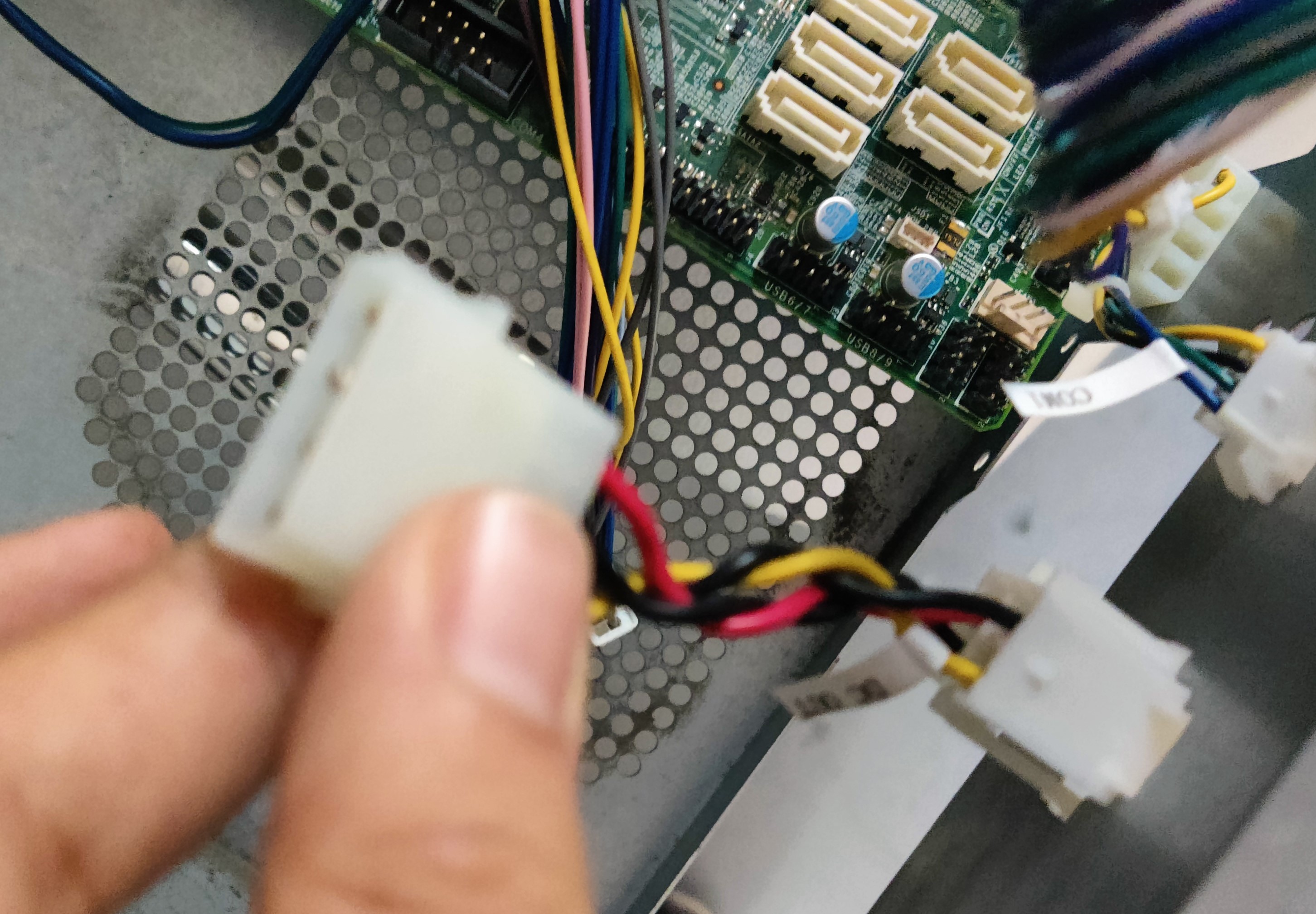
In my case after making the harness it ended up looking like this:
Instead of starting from pin 1 which would be the top left pin, in this case pin 1 is located at the bottom right.
All the wires from the CN10 and pin 1 from CN19 are grouped into the IC/W LED connector, which also carries 12V and GND for the woofers. For the readers, 12V and GND are taken from the COM1 connector instead, so in the end IC/W only feeds the woofer LEDs. (reference)
The remaining harnesses were built according to the diagram above. Do note that woofer color pins are spliced at some termination, resulting in two harnesses coming from one connector.
LED cables go through the woofer furniture from the inner side of the box (and covered with a small metal cover), which is separated from the outer side which is where the beams are secured.
Section between the cab and the woofer where the wires for the speaker and LEDs are covered, with the metal sheet removed
You can access this side by taking off the speaker, which can be set very thight in place and you may need to apply some force with a tool like a flat screwdriver.
Woofer deattached off the box, showing the inside
Inside the woofer box you can see the holes that correspond to the ones in the pictures above, you will have to pass the harness through here in order to make it to the LED boards.
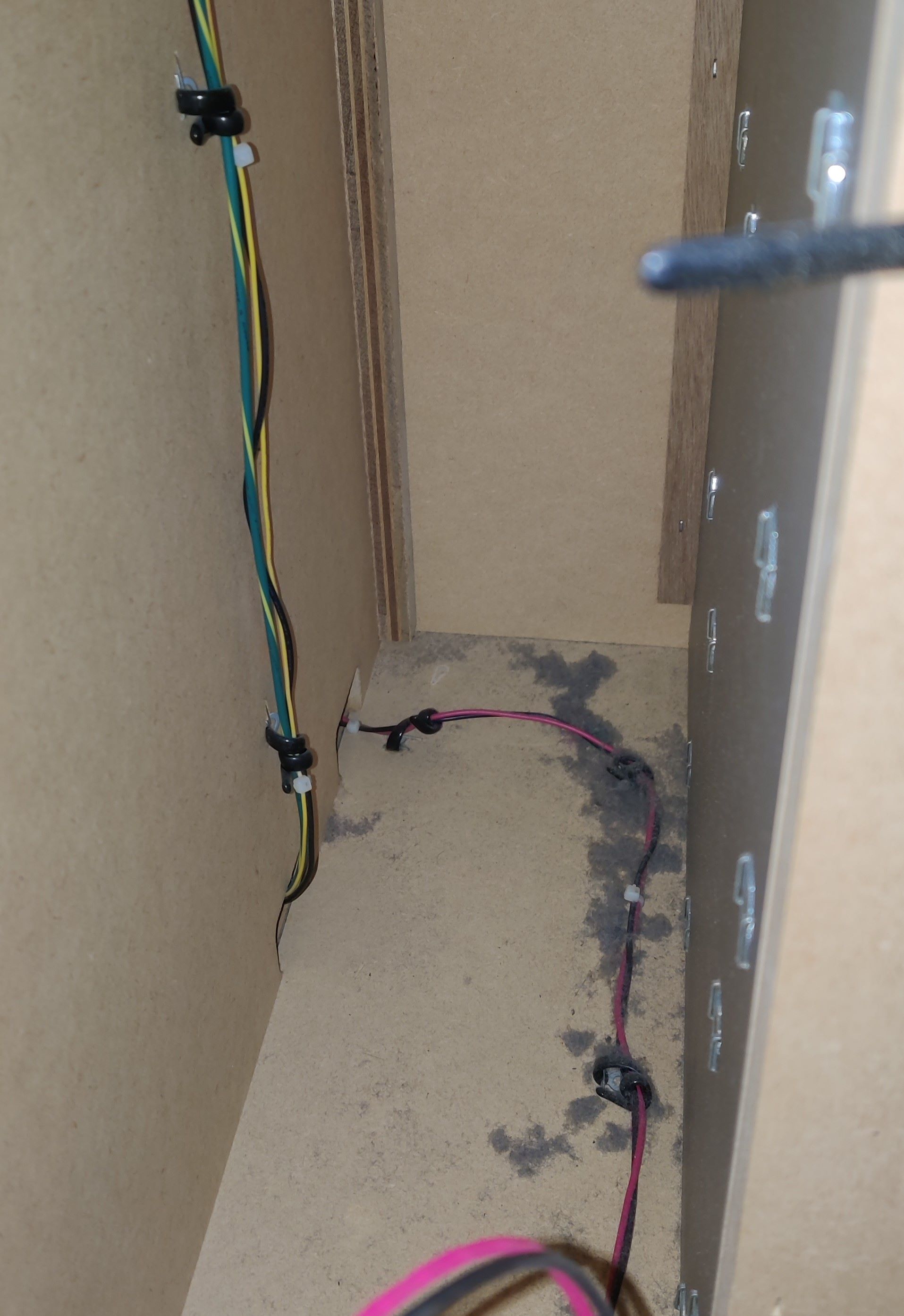
To pass the harnesses you may use one of the holes inside the cab that were shown in the Audio Jack section, in the same fashion as for the audio cables. The following pictures show through where I’ve been running the harness through up to the LEDs:
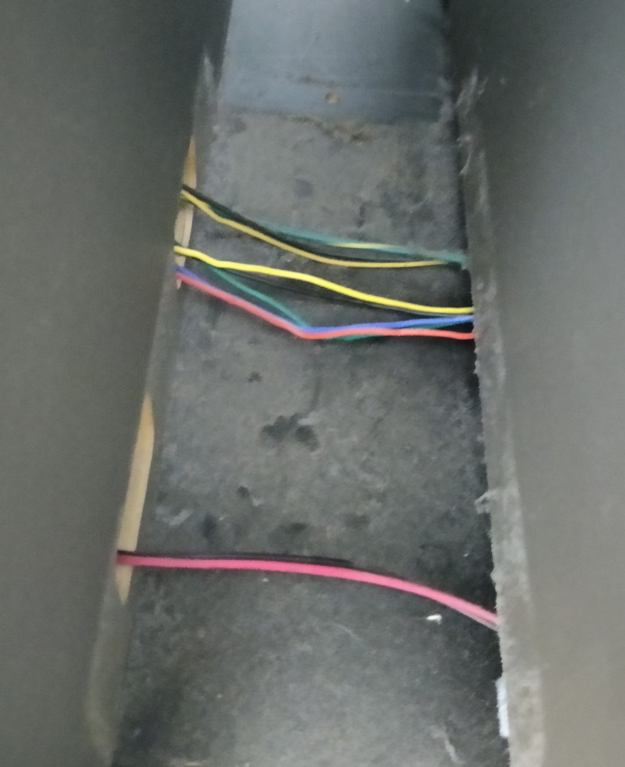
For this last section I’ve ran the harness through the same hole as the original harness, which is in the innermost corner (this is the P2 woofer, so it is located at the right).
In the way upwards you can find (or rather, touch) a knot where the original harness is held so it doesn’t fall through the hole, you may use it too for the new harness.
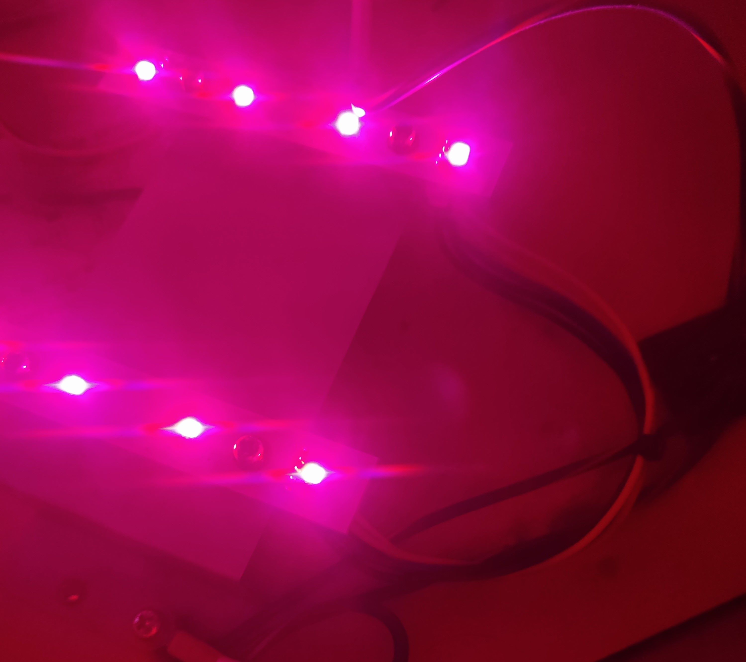
Woofer LED boards turned on and working with new harnesses
Readers
- LED PCB connector: PHR-5
- Lights are independent from reader signal
- Reader connector: XMR-05V → XMP-05V
- LED bridge cable length: 15cm
- Cable length: ~80cm each
- From last-end connector to LED PCB
WIP
Reader LEDs current and ground are being taken from COM1, +12V comes directly from PSU and ground is taken from PCB’s serial.
In this case I used pin 4 from COM1 to take current for the LEDs (benefiting from the workaround I did for the EPOLIS upgrade) and spliced the GND pin in order to merge both the ground for the serial and the lights. (reference)
The remaining harnesses were built according to the diagram above.
Turntables
- TT RGB connector: XMP-05V → XMR-05V
- LED PCB connnector: PHR-5
- LED bridge cable length: 15cm
- Cable length: ~150cm each
- From last-end connector to LED PCB
In order to be able to connect the TT sensor pins I used a B20B-PHDSS board socket to build an extension of the original CN19 harness (reference), I couldn’t find an actual plug connector for PHDR-20VS so I used this instead, which works anyway. If you don’t want to solder I linked a 26 AWG harness which has both connectors, but keep in mind that you would have to depin the terminals that correspond to the LED pins, at least for safety.
The remaining harnesses were built according to the diagram above.
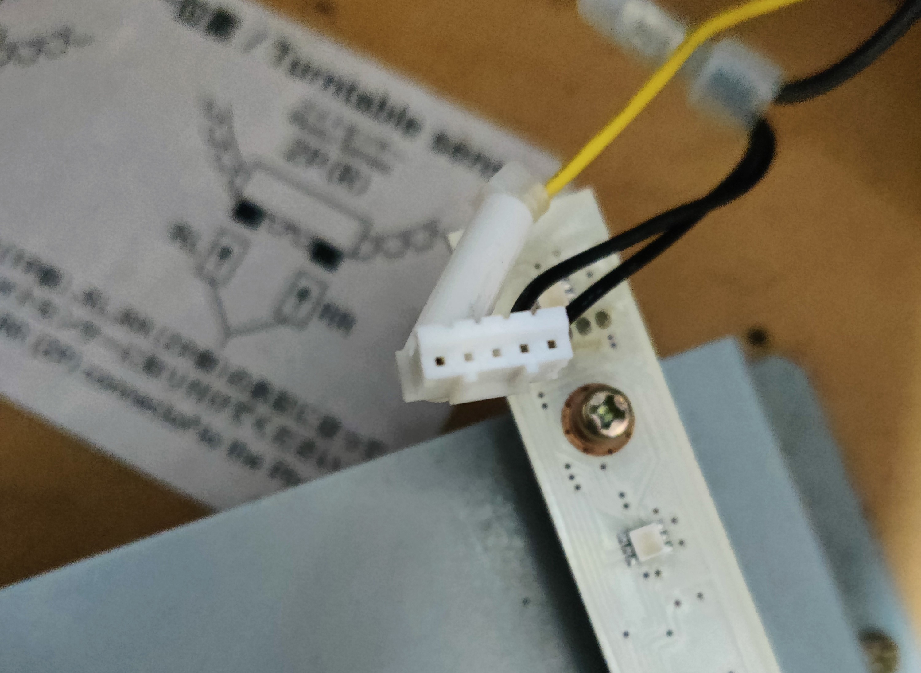
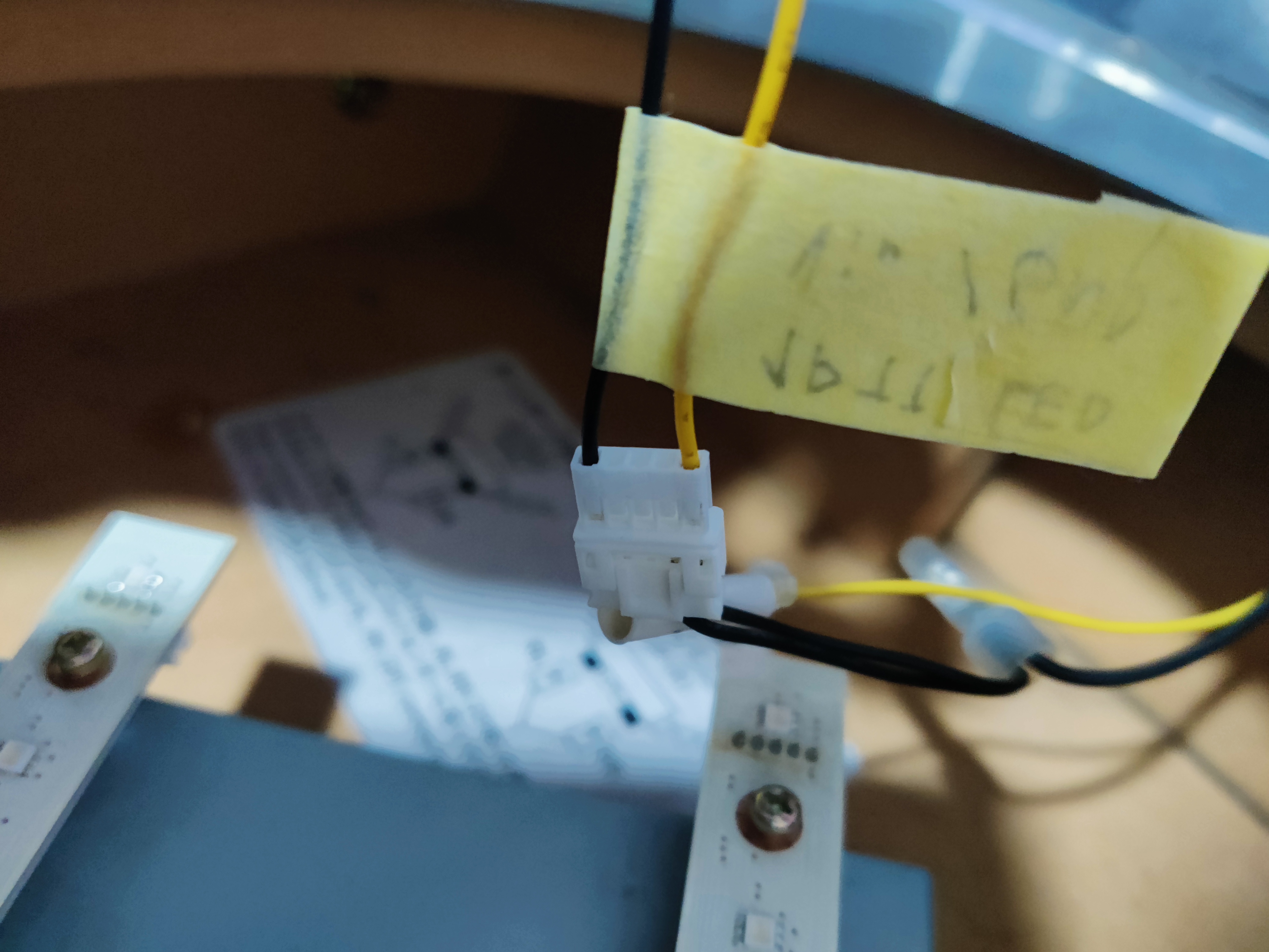
The following pictures show how the LED board connector looks when unplugged, I used this as reference when making the harnesses.
Results
CN19 (Turntables)
LED board harnesses, long one is the connection to the BIO2 source (plus voltage and ground), small one is the bridge between boards
Messy cable distribution after adding the new harness for CN19, including the extension for the original CN19 harness and how current is taken from the PSU
New CN19 harness
Extension of original CN19 harness
TT sensor wires from CN19 harness
Harness and 12V and GND connections from the PSU
Testing the new harness
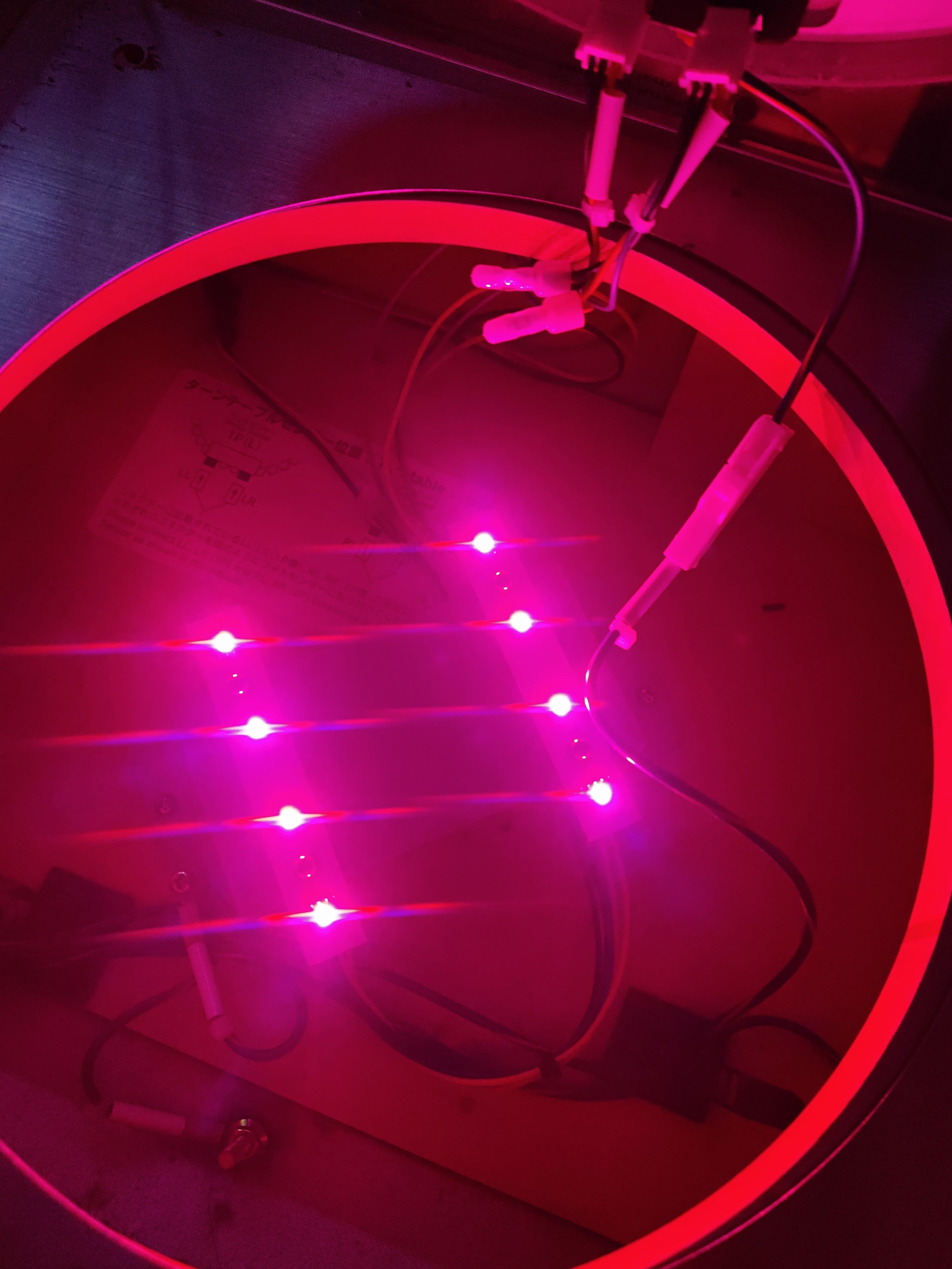
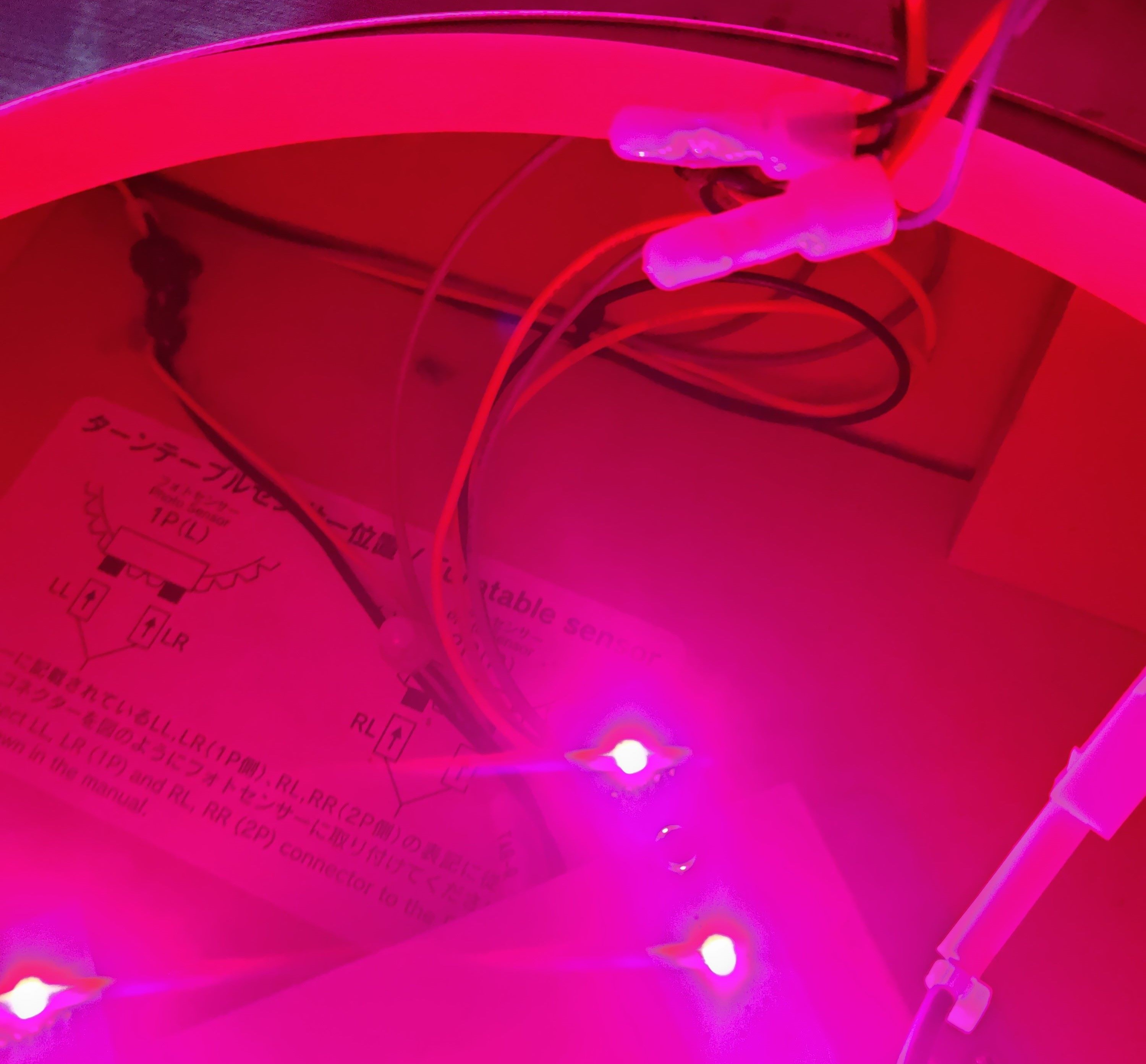
Final look of the turtable LEDs
CN10 (Woofers and Readers)
Woofers results
CN10 harness (wrong wiring, check Wooferssection)
IC/W LED connector, grouping all conections for readers and woofers LEDs
12V and GND taken from PSU into IC/W LED connector
Testing the new harness
Final look on the woofer LEDs
Readers results
COM1 harness after adding wires for 12V and replacing the GND wire
Link to original
IC/W LED connector and IC LED connectors


🚨 WS2812b Lights wiring
WS2812b Lights wiring
WIP
Proceed with Caution
Careful when making the harnesses for this part
Due to the amount of current that will be transported through the wires that connect the LEDs with the respective source of power, you’ll probably need a big enough wire gauge for feeding +5V to the LEDs, and also keep the same gauge size for grounds.
For this part I will use 22 AWG since it’s the biggest or at least one of the bigger gauges that the used JST terminals allow.
KEEP IN MIND that this is still a work in progress and hasn’t been tested as of now.
Bill Of Materials
If any link stops working, just try to searching for the piece in specific for the time being, you’ll probably find it.
CN18 (lights output):
- PHDR-16VS:
- 26 AWG Harness (2x8P): https://es.aliexpress.com/item/1005004746953918.html
- 24 AWG harness (2x8P): https://es.aliexpress.com/item/1005005169172801.html
- 22 AWG harness: https://es.aliexpress.com/item/1005009277050529.html
- Terminals (SPHD-001T-P0.5): https://es.aliexpress.com/item/1005003975795283.html
- LED tapes
- 68 LED tape x4
- 61 LED tape x2
- 54 LED tape x2
- 11 LED tape x2
- 57 White LED tape x2
- 45 LED tape x2
- 21 LED tape x1
- 17 LED tape x1
- 19 LED tape x1
- Total: 17 LED tapes
LED lightning
- WS2812B 60led/m and 100led/m tape: https://es.aliexpress.com/item/1005005910958172.html
- 3Pin AWG22 wire (just in case): https://es.aliexpress.com/item/33032954455.html
- JST connectors AWG22: https://es.aliexpress.com/item/33042936981.html
- B2010 Tape diffusor: https://es.aliexpress.com/item/1005008042786167.html
- T0511 Tape diffusor (for compane): https://es.aliexpress.com/item/1005008376388272.html
- D1313 180º Tape diffusor (for TP sides) https://es.aliexpress.com/item/1005008109124457.html
- Spotlights alternative:
- WS2812B boards (3bit and 1bit): https://es.aliexpress.com/item/1005007503733494.html
DC TAPE LED
- RECOMMENDED to use 22 AWG cable for feeding 5V to all tapes
- XADR-20V → XADRP-20V → CN18 (PHDR-16VS) & LEDs
- XADR-20V:
- Connector: https://es.aliexpress.com/item/1005008510643553.html
- Terminals (SXAM-001T-P0.6): https://es.aliexpress.com/item/1005008545737745.html
- XADRP-20V
- Connector: https://www.aliexpress.com/item/1005007898440466.html
- Terminals (SXA-001T-P0.6): https://es.aliexpress.com/item/1005004425152785.html
External PSU
- MEAN WELL 5V 90W LRS-100-5 PSU
This section contains all related documentation, notes and results related the process of installing and setting up addresssable LED lights on a Tricoro cabinet, in order to behave and look like the light system of a LM cabinet, while making use of the BIO2 dedicated connections that are already programmed for this purpose on LM cabinets.
Lightning model outline
Legend
- Red: BASS
- Blue: SIDE_1P
- Green: SIDE_2P
- Orange: COMPANE
- Gray: UPPER
- Brown: TP SIDE
- Pink: PILLAR_1P
- Yellow: PILLAR_2P
LM WS2812b LEDs outline
Legacy outline (theory)
Tricoro cabinet outline of the setup for the WS2812b LEDs
CN18
WS2812b lights wiring outline
For this you will likely need an external PSU in order to feed all the required LEDs, since the PCB’s PSU probably will not be enough. The LED data is taken out from CN18.
LED tapes
Measurements
- Diffusors used are 2cm width long
Pillars
- 1 meter (~98cm) per bar (4 meters)

Upper
Sides
- From bottom of cab to mark on the metal piece: 85cm
Compane
- 41 cm, below deck, just above door
TP sides
- On each side: 27cm
- Without covering all of panel’s height: 25cm
- Running connecting cable below deck: ~112cm
PILLAR 1P
1P barrier
- 68 LED tape x2
- 61 LED tape x1
PILLAR 2P
2P barrier
- 68 LED tape x2
- 61 LED tape x1
UPPER
Upper corners, LEDs above speakers, header LEDS seem to be independent
- 54 LED tape x2
- 11 LED tape x2
- 57 White LED tape x2
Will mainly use 60led/m tape for the top speaker LEDs, trying to cover both 54 LED tapes.
Options are:
- Using 100led/m tape for the 11 LED tapes, on the sides of the top beam (as drafted here
- Get WS2812B LED boards and have them inside the spotlights
SIDE 1P
1P side under deck and barrier
- 45 LED tape x1
SIDE 2P
2P side under deck and barrier
- 45 LED tape x1
COMP (compane)
Strip under deck
- 21 LED tape x1
Will use the T0511 tape diffuser since it’s going to be the less visible one and lightning will be more than enough. Might use 60led/m tape since it will cover more length
TP SIDE
Strips on touch panel sides
- 17 LED tape x2
Will use the D1313 tape diffuser in order to assimilate how it looks on a real LM, since it looks like the diffuser itself is sitting on the panel, therefore a 180º diffuser might do the trick.
Might use 60led/m tape depending of how it looks.
BASS
Strips on bass shaker
- 19 LED tape x2
Might not add LEDs to bass shaker since having them where feet will be moving around can bring more trouble than anything.
Link to original


