TODO
- Add pictures with headphone amplifiers
This section contains all related documentation, notes and results related the process of setting up headphone jack connectors on a Tricoro cabinet, in order to make it work like a LM cabinet, while making use of the BIO2 dedicated connections that are already programmed for these purpose on LM cabinets.
Planning
- Get same harness for CN15 (PHDR-26VS) and build to XMR-8V harness, the existing cable for 1P keys (BI2A wiring) can be reused
- Short to ground both HP and REC pins to have headphones always enabled
- Alternatively build some audio jack cables, using the mic pin for HP DETECT
- Either way headphone amplifiers will be needed.
- Given previous points, rewiring shouldn’t be needed
Audio Jack wiring outline

Alternative outline with audio cables

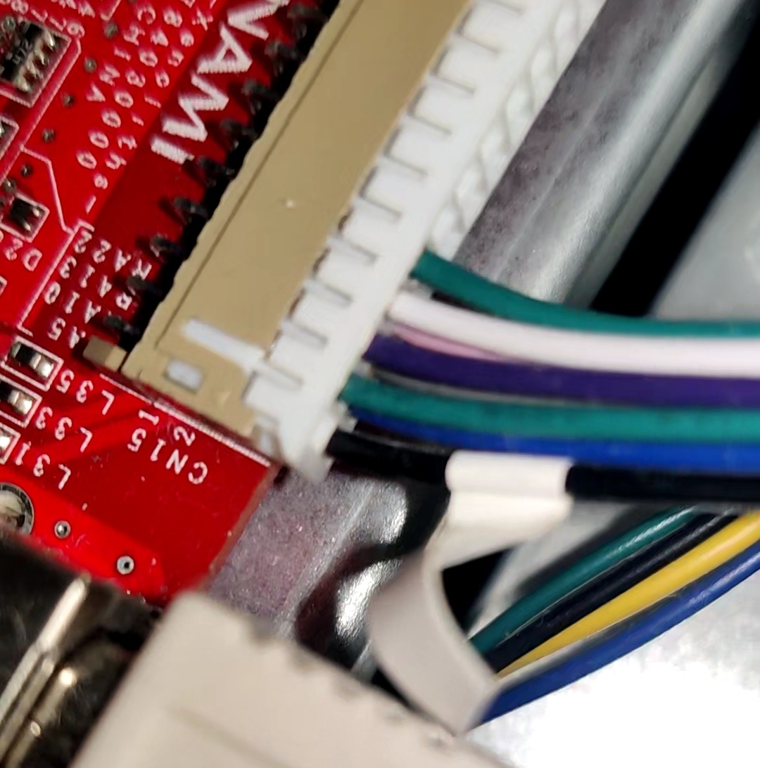
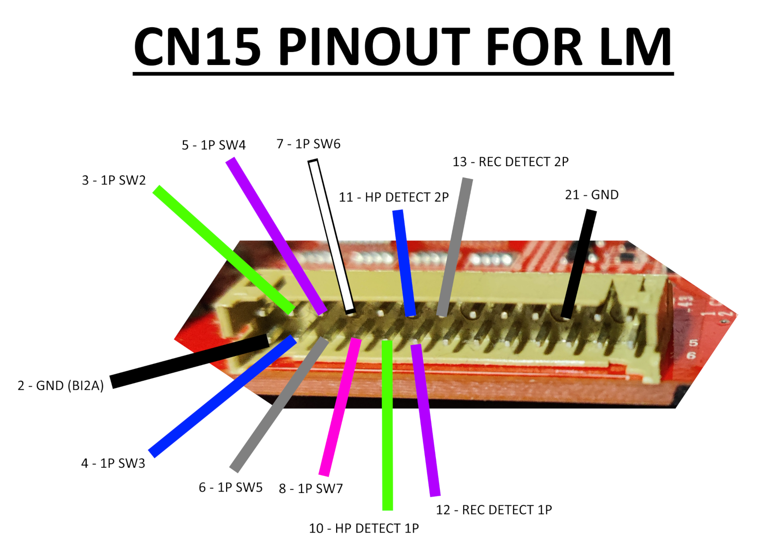
CN15
Bill Of Materials
If any link stops working, just try to searching for the piece in specific for the time being, you’ll probably find it.
PCB connector:
- PHDR-26VS:
- Harness: https://es.aliexpress.com/item/1005008107323180.html
- Terminals (SPHD-001T-P0.5): https://es.aliexpress.com/item/1005003975795283.html
Other end of cable:
- XMR-08V:
- Connector and terminals: https://es.aliexpress.com/item/1005009346695309.html
- Terminals (SXM-001T-P0.6): https://es.aliexpress.com/item/1005008545862370.html
Audio cable:
- TRRS 3.5mm female jack plug: https://es.aliexpress.com/item/1005008150971423.html
- TRS 3.5mm male jack plug: https://es.aliexpress.com/item/1005005672946991.html
- Sheathed wire (4 cores): https://es.aliexpress.com/item/1005007924124268.html
- Headphone amplifiers
- MAX4410 board: https://es.aliexpress.com/item/1005006230596608.html
- XH JST kit: https://es.aliexpress.com/item/1005006847308001.html
- DC input connector 2.1mmx5.5mm: https://es.aliexpress.com/item/1005007870346260.html
- HA400 amp (knock-off): https://es.aliexpress.com/item/1005006614134556.html
BI2A wiring

BI2X wiring

Headphones wiring

CN15 is the easiest one since it could be left as it is, but if you want headphones to work you need to add a few more cables (check BI2X wiring). From here you have two options:
- Short all HP and REC DETECT pins to GND, REC DETECT pins may be just left unused (diagram)
- Build headphone cables that mainly goes to the audio card, with an extra cable soldered to the mic pin of the jack that goes to each HP DETECT pin on CN15 (diagram)
The first option is more of a shim than anything, but it lets you setup headphone volume through the touch screen since this makes the game believe that both headphones are connected.
The second solution ensures that the headphones will work since the game will detect that they have been plugged to either 1P or 2P jack and will let you change headphone volume through the volume settings in the touch screen.
XONAR ports
First thing to take into account is that the respective outputs for each player on the XONAR are as it follows, from start to bottom:
- P1: SIDE output (last port)
- P2: REAR OUTPUT (4th port)
For the audio cables, I’ve made them with a length of ~180cm (shorter than I would like, 200cm may be better) and soldering TRRS/4-pole female jack plugs with TRS/3-pole male jack plugs, leaving the mic pin from the female jack separated for crimping and inserting it in their respective HP DETECT pin. (References can be seen here and here)
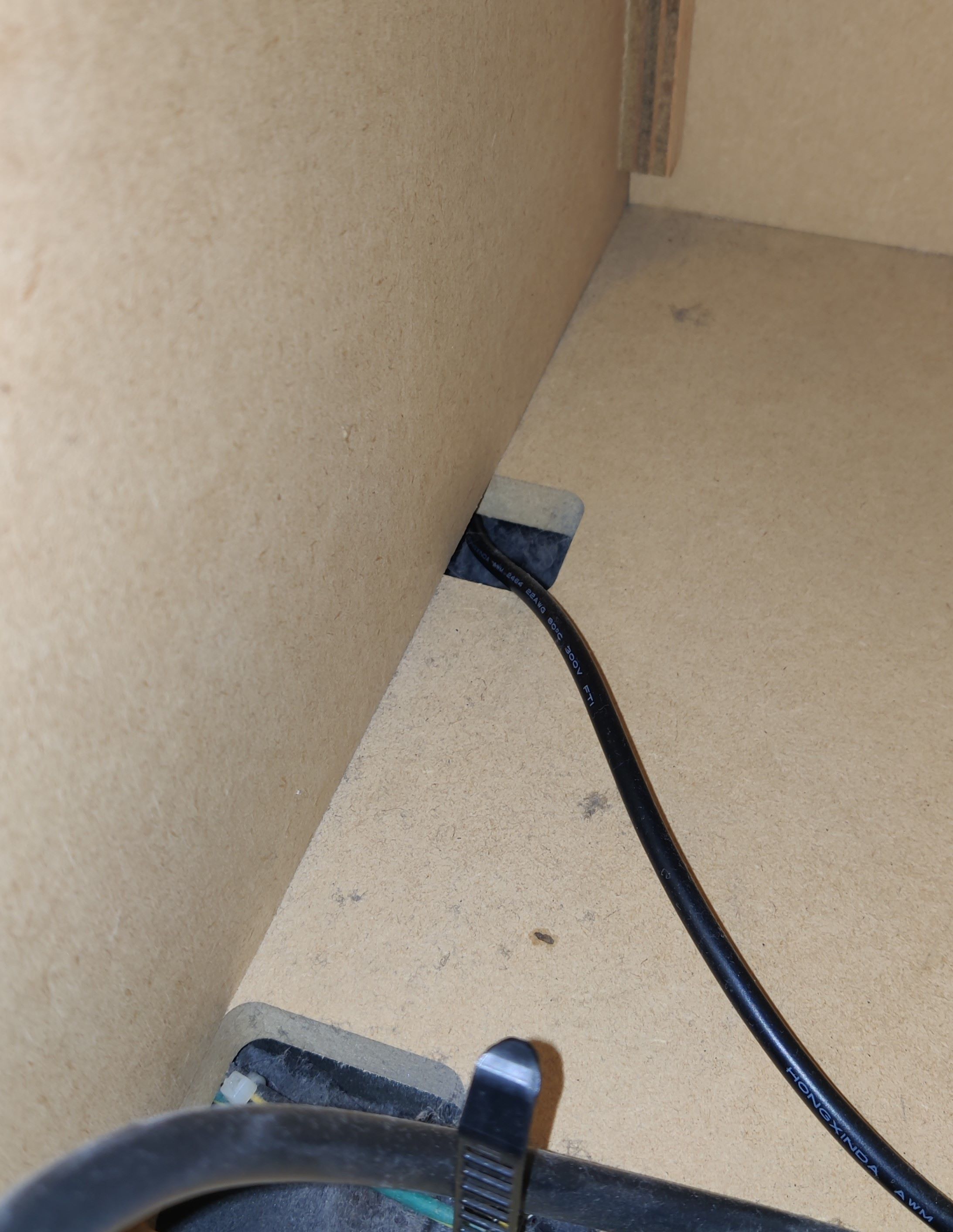
The audio cables can be taken outside through some holes that can be found inside the cabinet, you can see that through some of them the wires for the woofer speakers and woofer LED lights are being passed through, I used the one that is further away (third hole) which also connects directly outside unlike the other ones, which are covered with a metal plate.
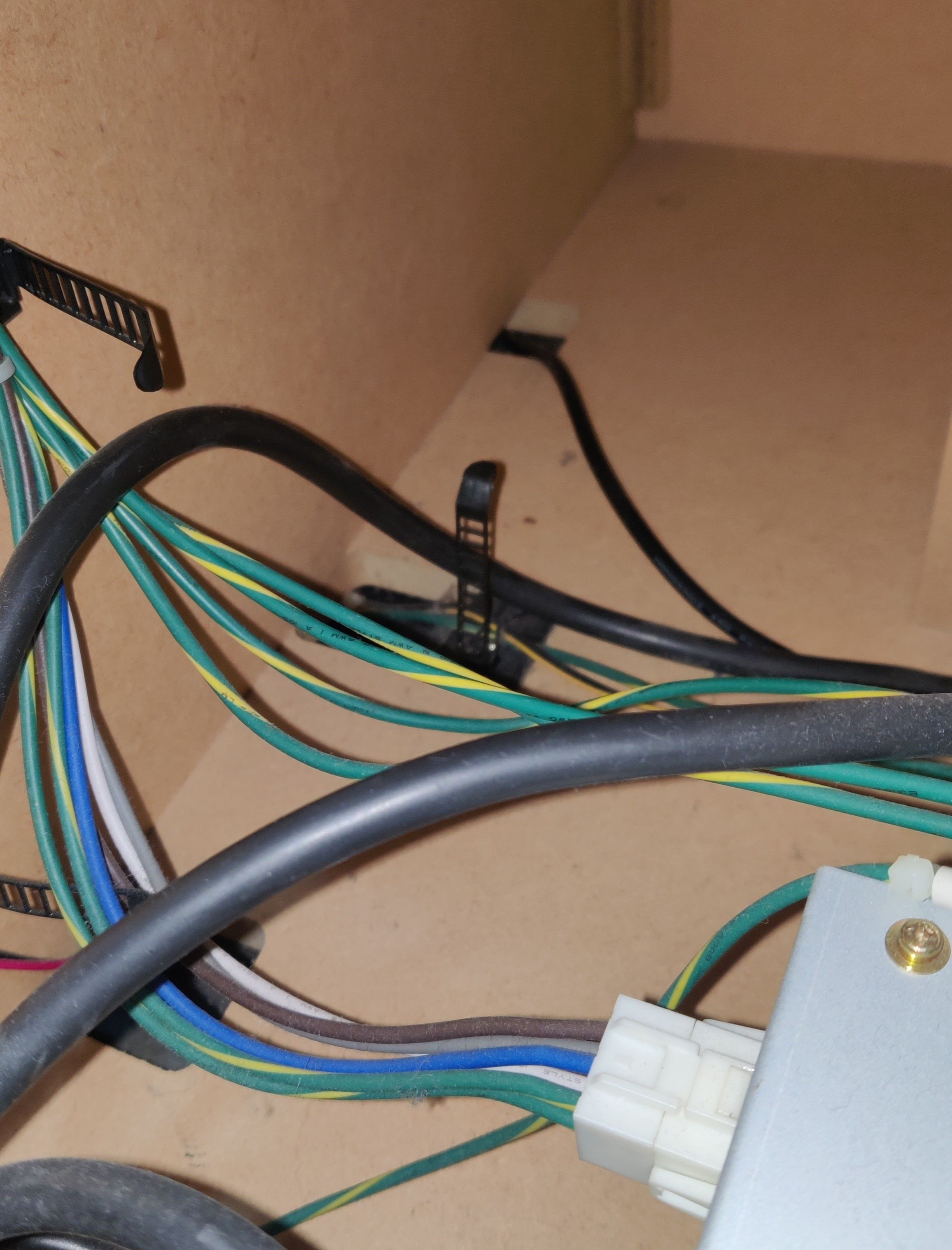 Audio cable being passed through the farthest of the holes, the nearest two carry wires for the woofer speaker and the woofer LEDs respectively
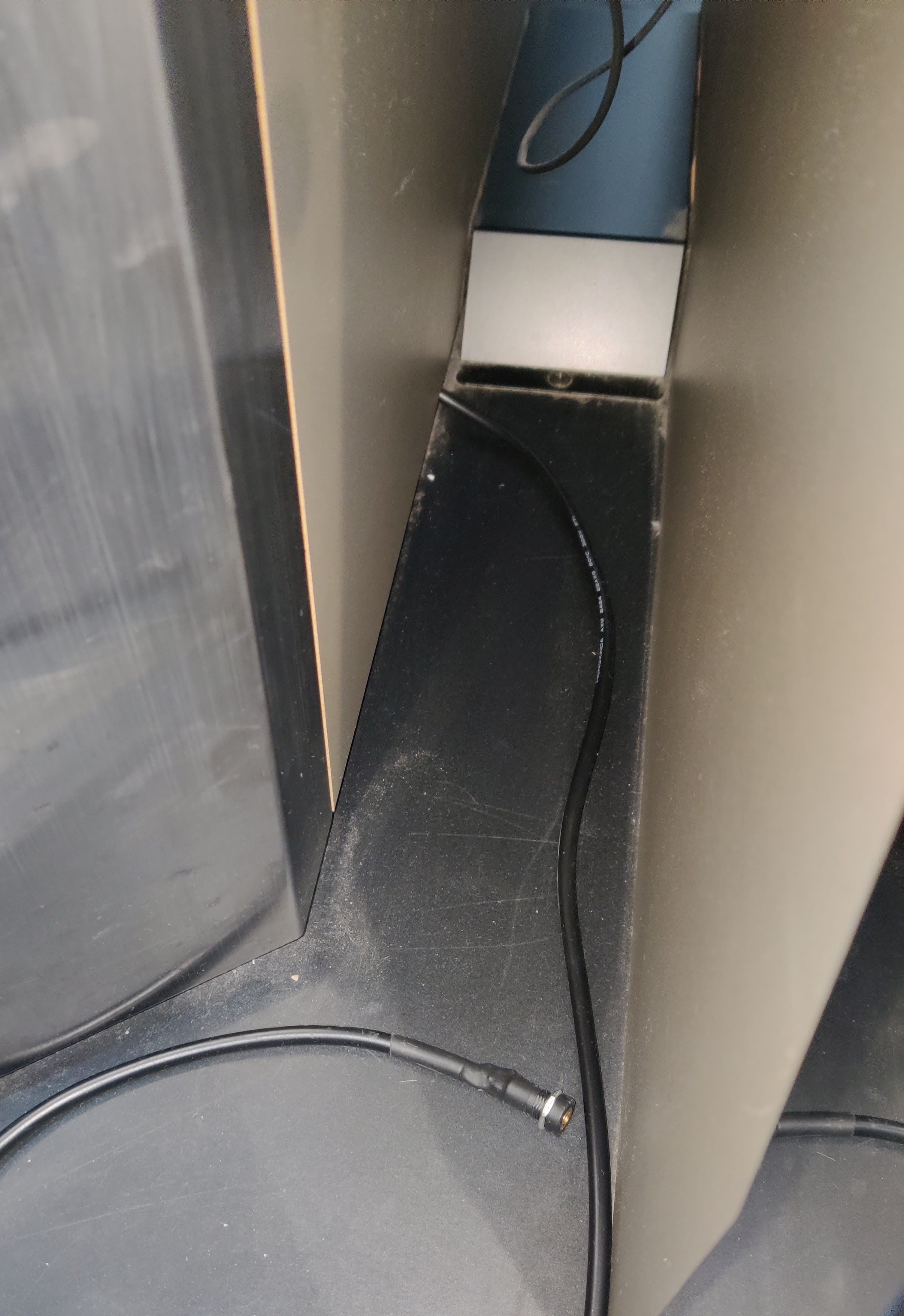 Audio cable outside the cabinet. Metal plate that covers the other cables can be seen in the back
At this point the headphone functionality should be working right away, the only detail left is that the audio by itself will be very low, so you will need an amplifier for both channels. Demonstration of headphone detect functionality working, before adding amplifiers (the highlighting of the volume control isn’t really appreciated in the video)
Following the diagrams of an LM cab, assuming the headphone amplifier and headphone jack PCBs are the same as Sound Voltex Valkyrie cabs (or at least Nemsys cabs since they would have very similar components as these two if not the same), the amp handles the signal coming SENS pin and then signals JACK DETECT (HP DETECT on BIO2’s CN15) and REC DETECT (same name on BIO2) depending on the connected device, and also all grounds in the amp are merged (reflected in this diagram)
Behringer HA400 amps work really well and can be very cheap. You may also get MAX4410 amp boards instead if you want an even cheaper option with the trade-off of having to build the necessary components yourself.
Only caveat with these amps is the grounds and how they are merged, HA400 amps have them merged only for the audio input and DC input, not the audio output, which means that you may have to join the grounds of the input and output jacks (if you’re also building the cables like I did)
TODO: TO BE TESTED
MAX4410 amp boards in the other hand do have all its grounds merged, which may be the most straight-forward solution with only having to setup the cables in that regard.
TODO: TO BE TESTED
For the record, the headphone detect functionality works without any amplifier in the middle of the setup (i.e. conecting these cablesas they are), which points to the minimal condition for it to work being that at least the ground continuity should not be cut at any point in between the headphone jack and the XONAR port path.
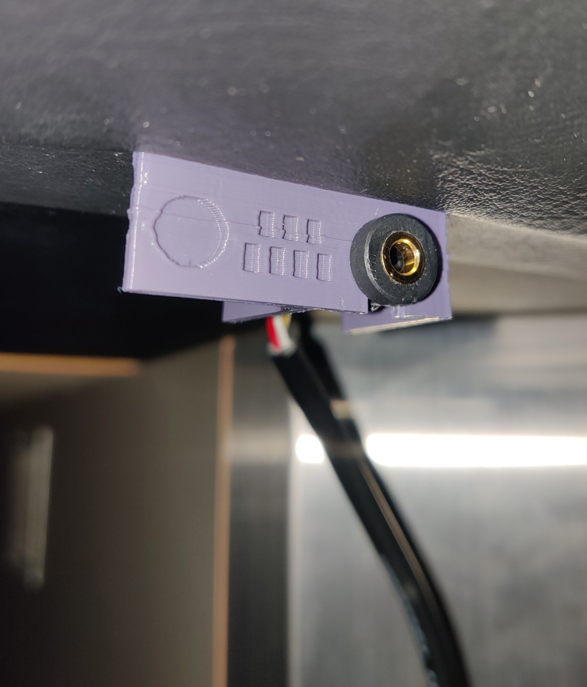
The audio plugs are positioned just below the deck, trying to keep them under the player buttons like in a Lightning Model cabinet, and to keep it fancy (and secured) a little 3D printed bracket was set up, made by @roxandtol: https://www.printables.com/model/1624880-pj392a-bracket-for-iidx
These brackets are attached using the M5 screws that you can find below the deck. You can see references here and here
Results
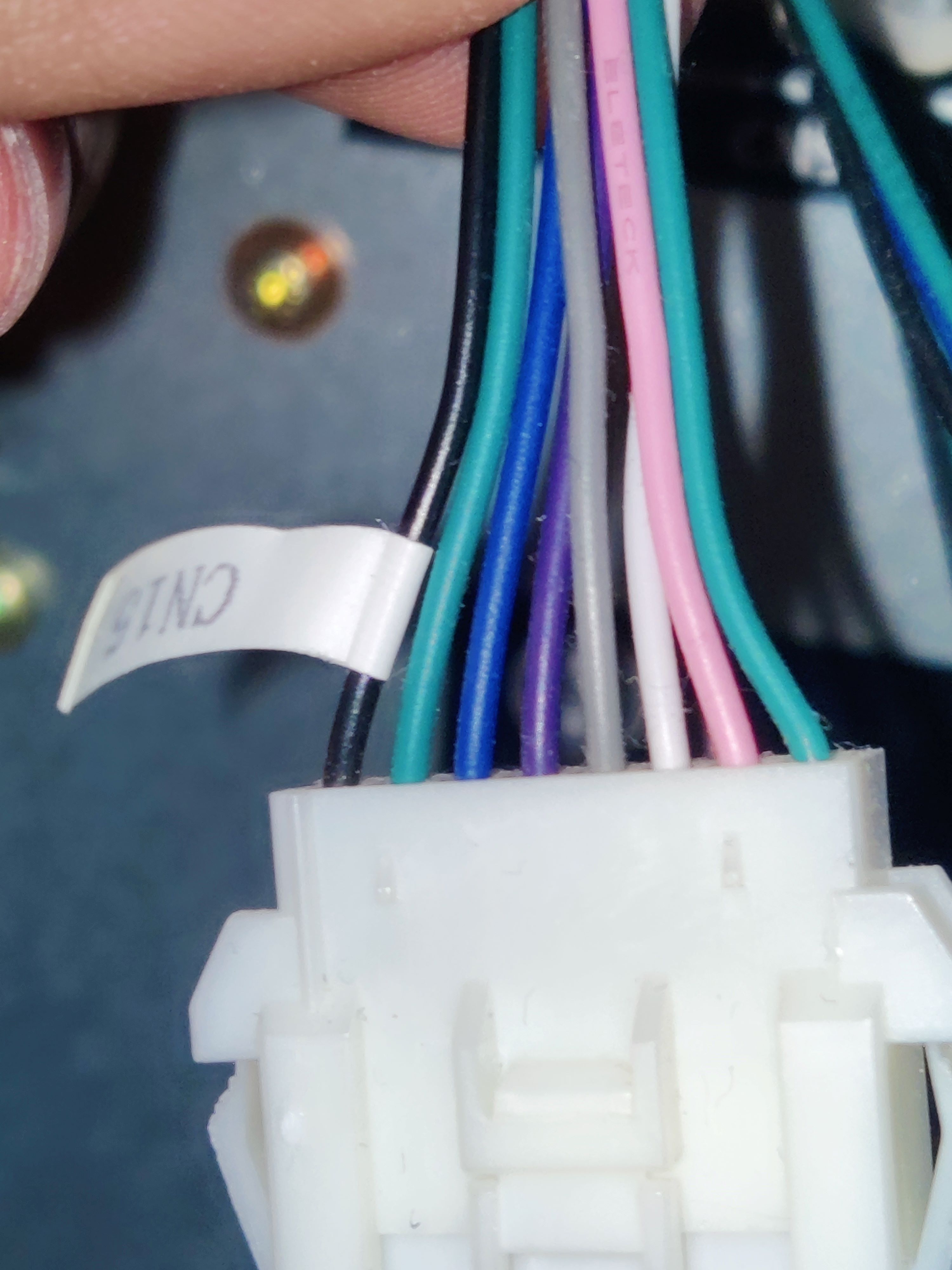
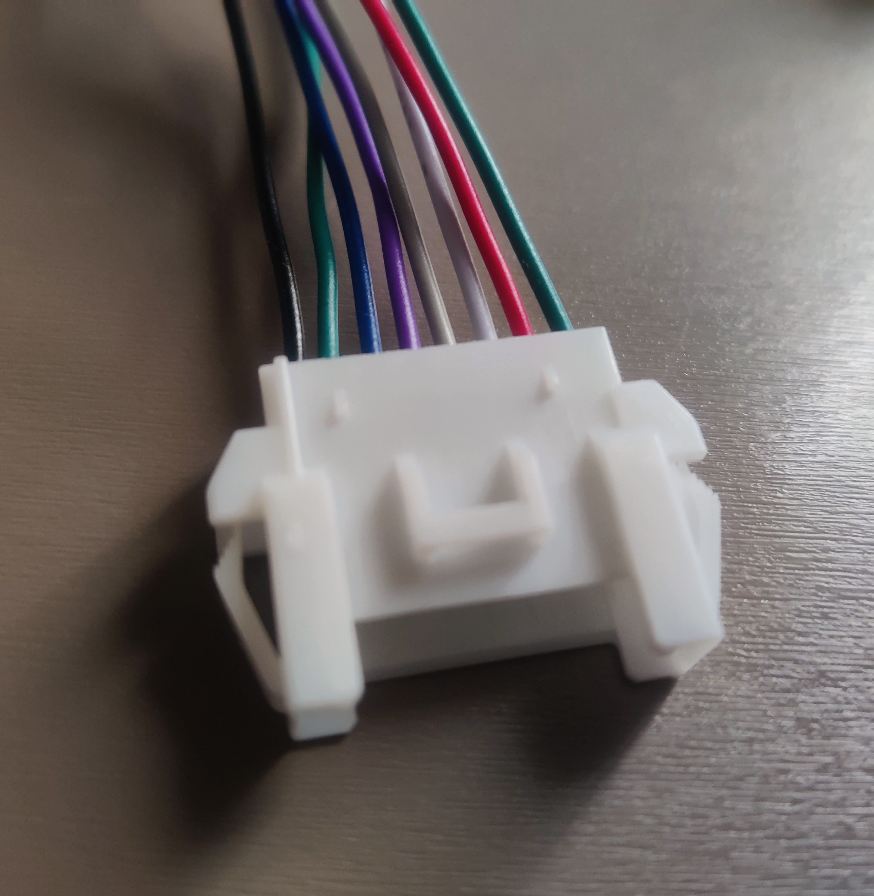 CN15 connector for legacy harness
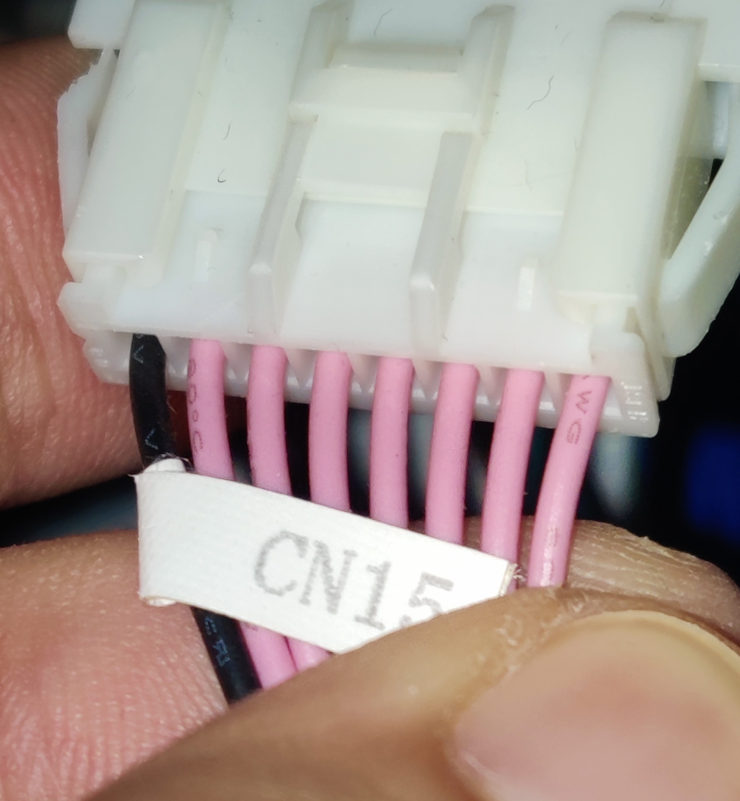
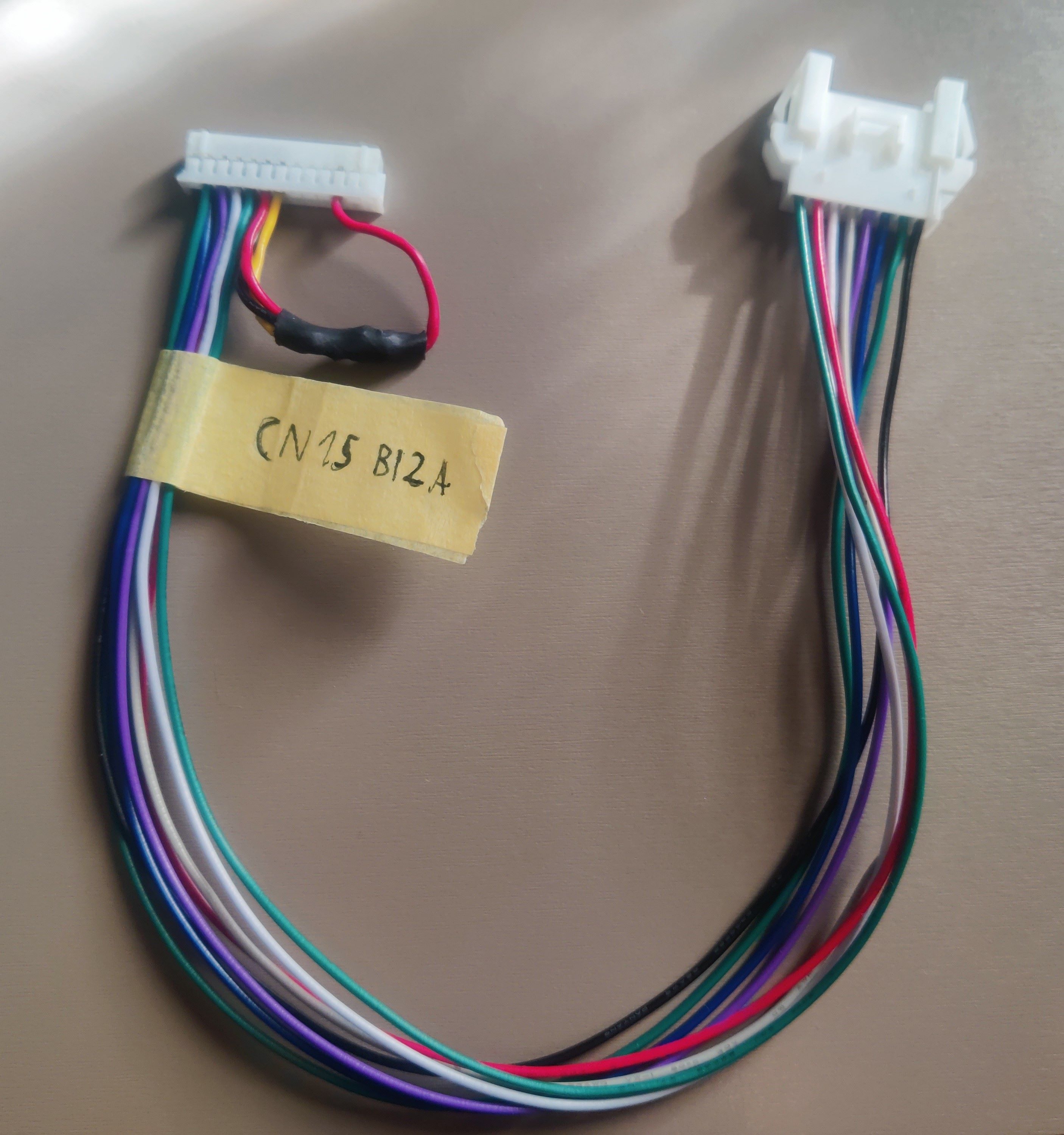 New CN15 harness with HP DETECT and REC DETECT shorted to ground
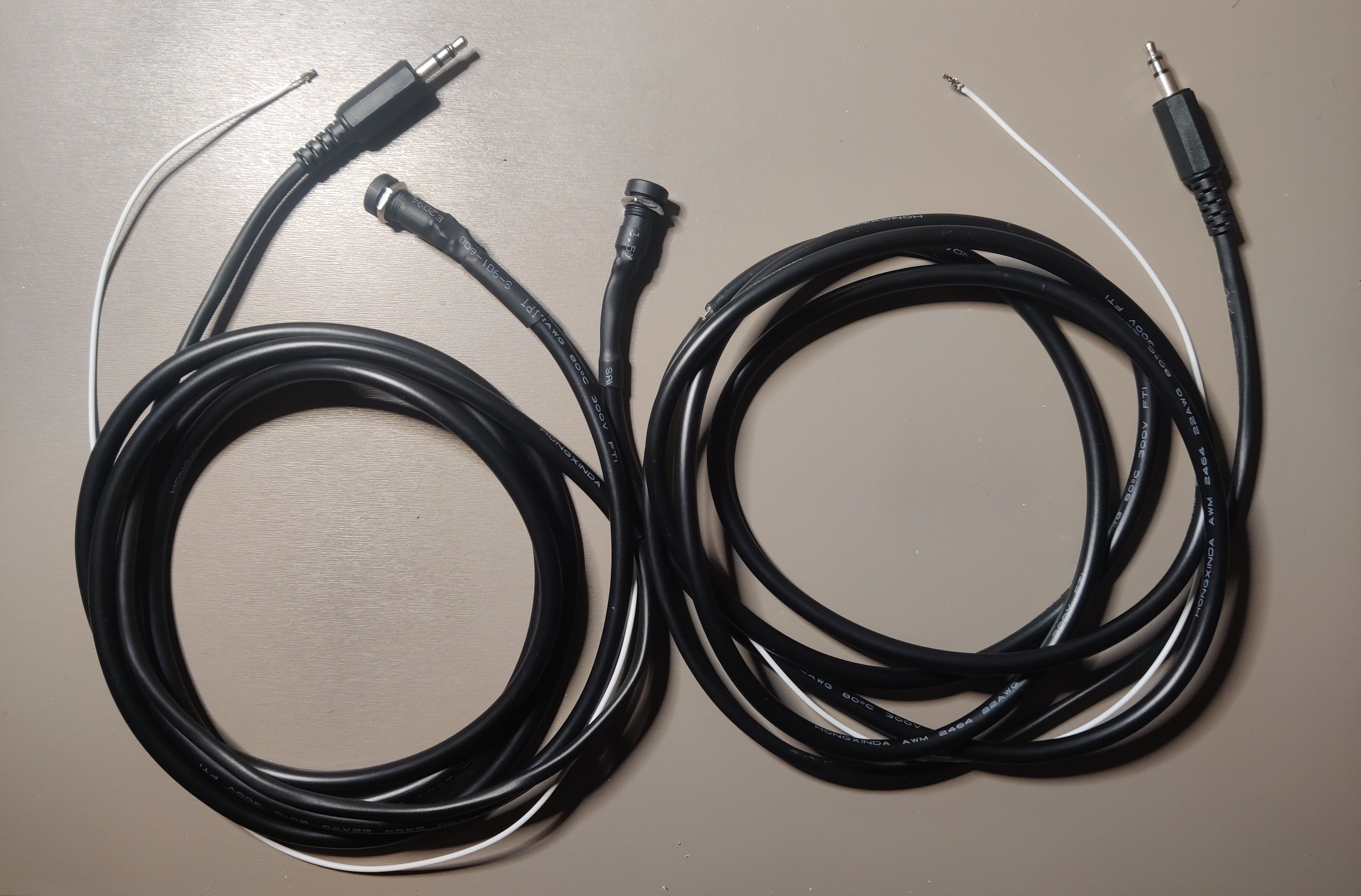 Audio cables with microphone pins crimped for CN15
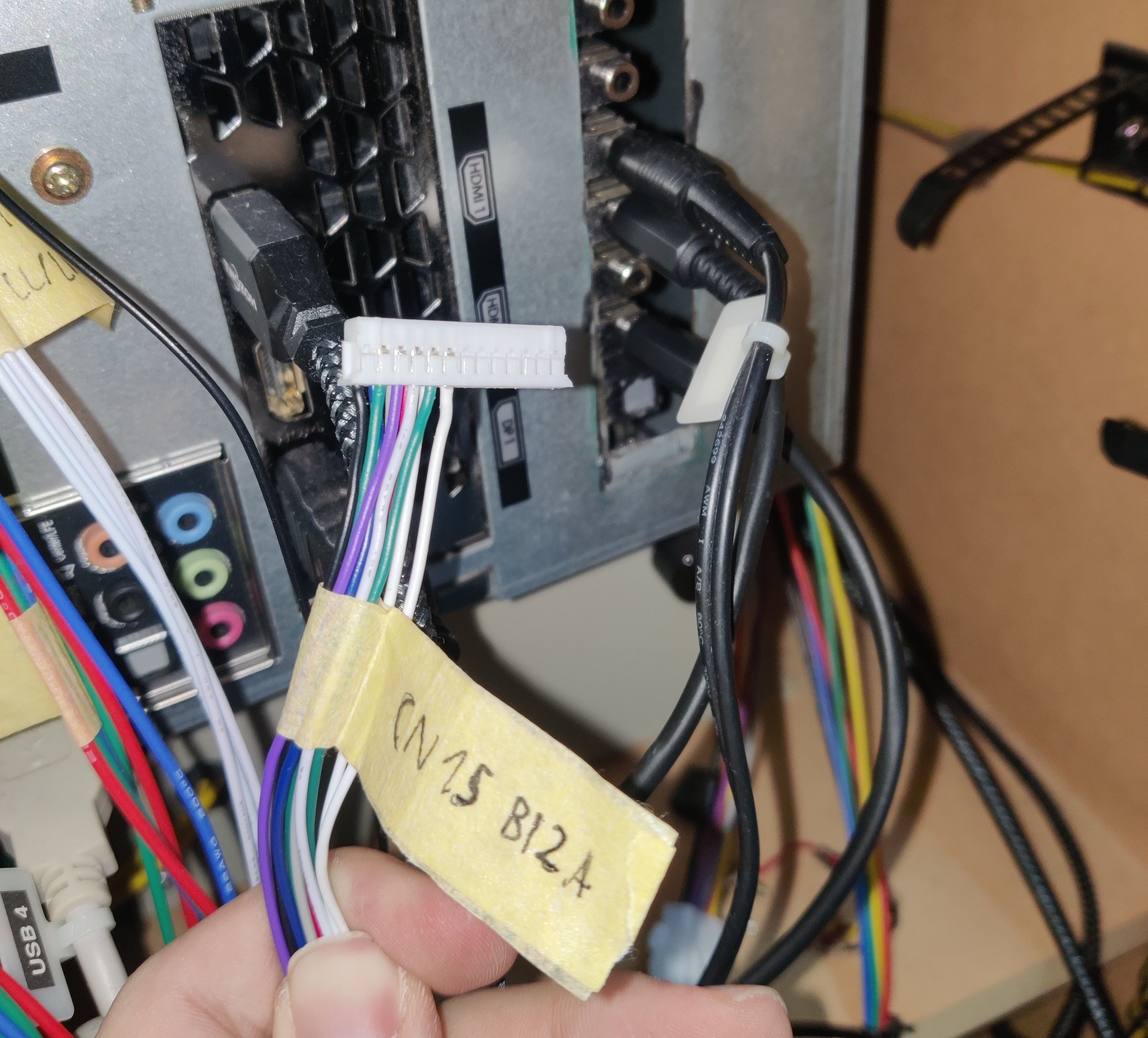 CN15 with HP DETECT pins (last two white wires), coming from the audio cables
 Audio jack with 3D printed bracket
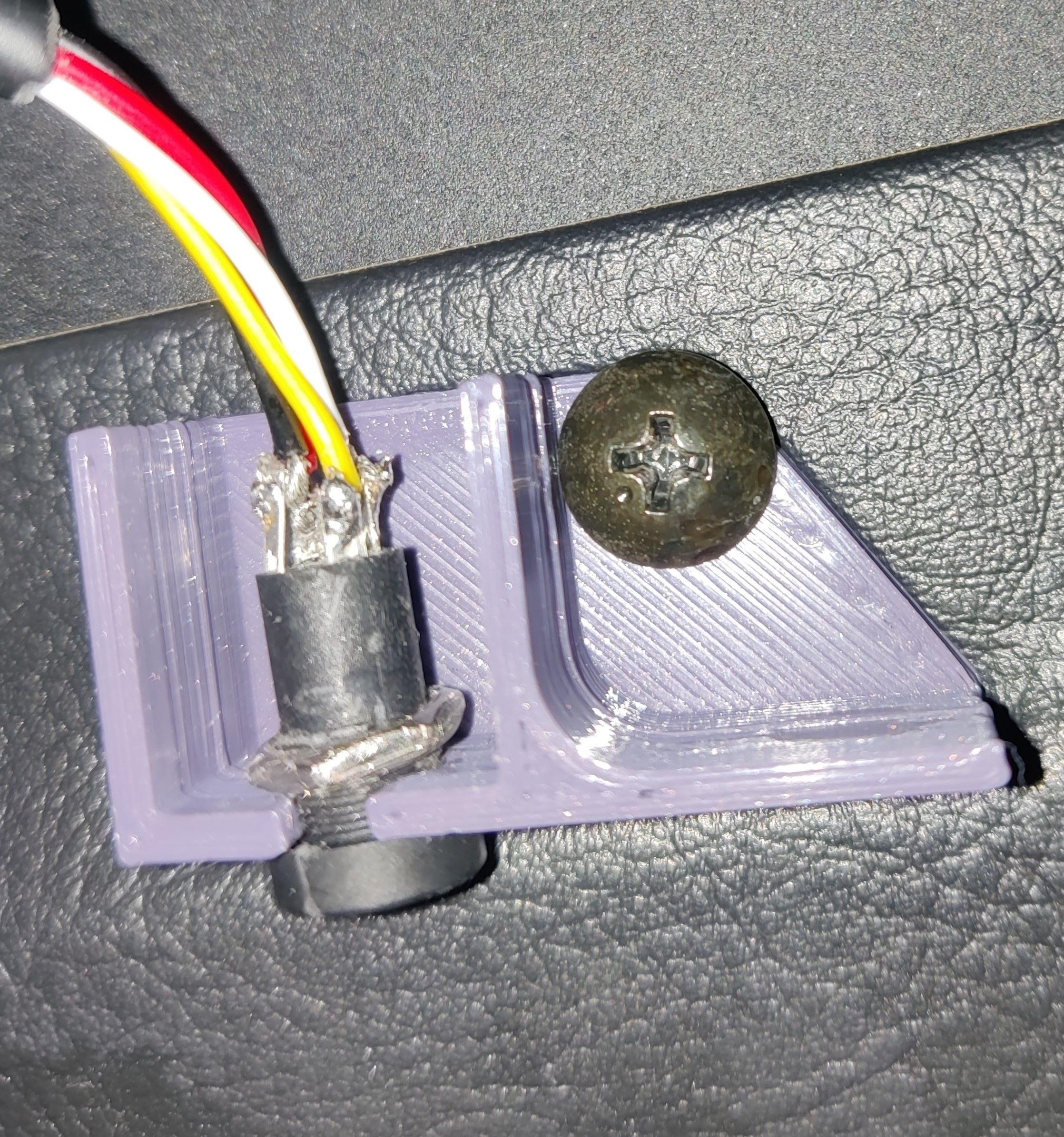 Audio jack with 3D printed bracket from below, using one of the screws from below the deck